9KVIEWS
41REPLIES
0APPRECIATES
05-09-2013LAST POST
I know this isn't a technical section but I'm hoping it gets seen by someone who's installed this kit since I've got the front of my car completely torn apart now.

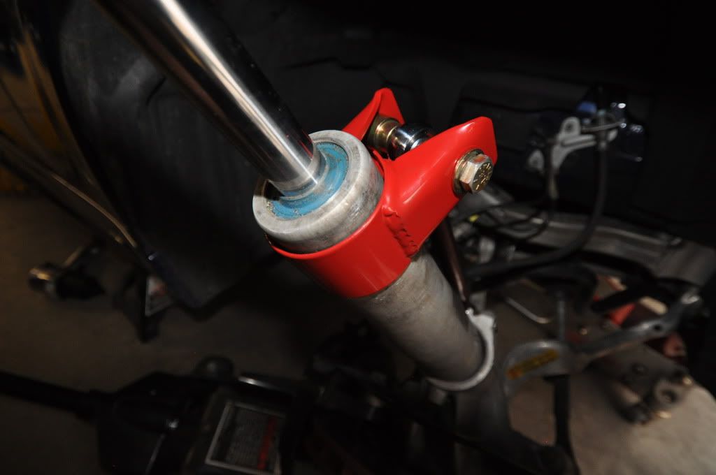
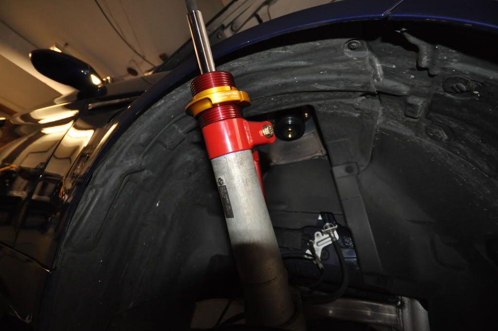
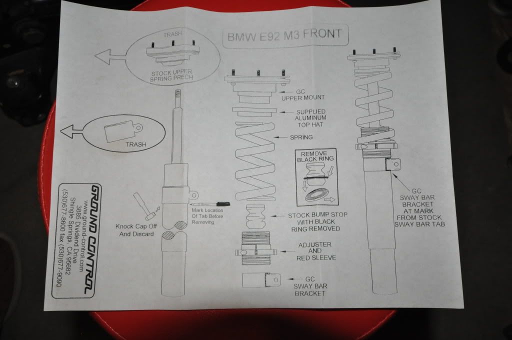
I'm questioning where the sway bar link bracket should sit on the body of the shock absorber. I marked the stock bracket per the instructions but, because the diameter of the shock body gets bigger (pic 2) a little ways from the top, when lining up the GC bracket to the stock mark it doesn't make much contact with the body of the shock except at the very bottom (pic 3).
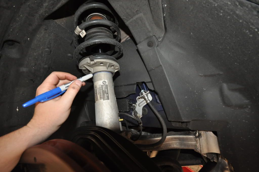
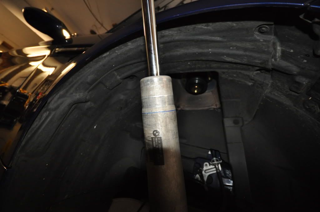
Image hosted on: i3.photobucket.com

I'm also unsure how long to set the sway bar links.

Any help is greatly appreciated. I'm taking lots of pictures so once I'm done I'd like to put together a DIY write up.
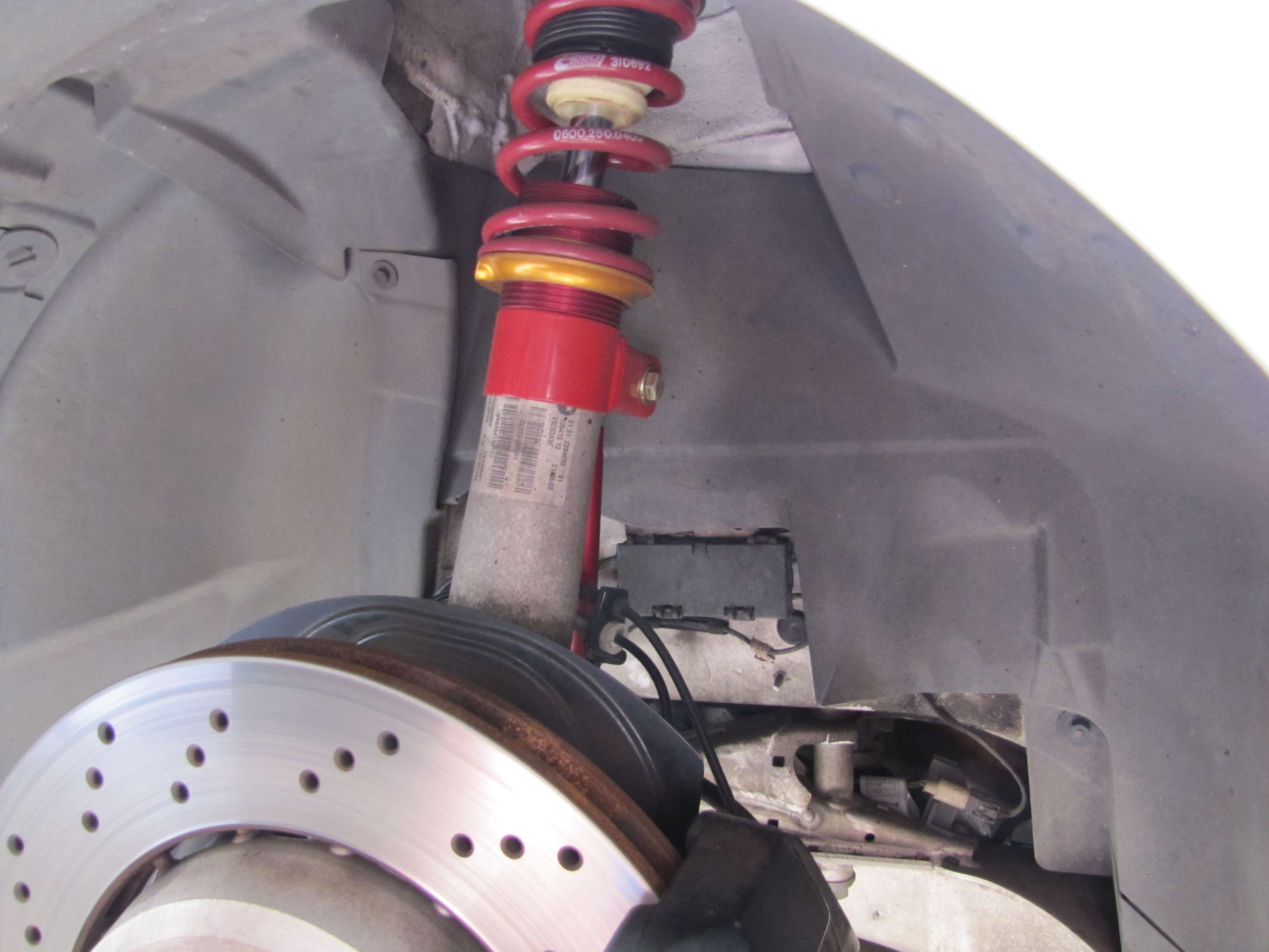
does this pic help??


Image hosted on: img189.imageshack.us
Thanks. Unfortunately it's not much help. I can't tell where the bracket sits on the body from the picture. Did someone do the install for you?
I think want the sway bar bracket underneath the blue line, not on top of it. Otherwise, the spring collar isn't going to be well supported either.

(this is a guess, i've never installed them but judging by the other pictures and the other install threads, I am guessing) :)
kitw wrote
I think want the sway bar bracket underneath the blue line, not on top of it. Otherwise, the spring collar isn't going to be well supported either.

(this is a guess, i've never installed them but judging by the other pictures and the other install threads, I am guessing) :)
That's what I think too and that's where I was planning on putting it. It makes the most sense but the diagram isn't clear one way or another. If that's where the bracket goes, I'm not sure if the threaded sleeve is supposed to rest on the top of the bracket, or the body of the shock, or both kinda. It's close.

Image hosted on: i3.photobucket.com

The diagram almost seems to point to the line under the bracket. That's why I started second guessing.
SlamMan wrote
That's what I think too and that's where I was planning on putting it. It makes the most sense but the diagram isn't clear one way or another. If that's where the bracket goes, I'm not sure if the threaded sleeve is supposed to rest on the top of the bracket, or the body of the shock, or both kinda. It's close.

Image hosted on: i3.photobucket.com

The diagram almost seems to point to the line under the bracket. That's why I started second guessing.
I didnt install mine...but threaded sleeve looks like it should be on top of the bracket...also, the end link is a certain length so it when you attach one end of it to sway, shouldnt it be obvious at which height the end towards bracket should go??
The sway bar link is adjustable but it's closest to the stock one in length if the bracket is below the line. Another reason it makes most sense with the bracket below the line.
Did you get this worked out and finished up last night? Curious to see pics of the result and the DIY. Hope you got it sorted.
Unfortunately no. I need to call GC here soon.
A big thanks to Donovan at Ground Control for answering my newbie questions. I just got off the phone and, according to him, the threaded sleeve is just going to rest on the tapered part of the shock body, just above my blue line in the 2nd pic. The link bracket is just going to attach below that. If I put the link bracket just at or below the blue line then the bracket won't come in contact with the threaded sleeve. He said the sleeve doesn't necessarily rest on or come in contact with the link bracket. He told me the marking of the original bracket was less about the height and more about the circumferential orientation. Good thing I marked both just to be safe.

Hopefully I won't run into any other questions and I can wrap up this evening.
you're a brave man for doing this on your own...I know its not an easy install...:cool!:

GL...post pics when youre done.
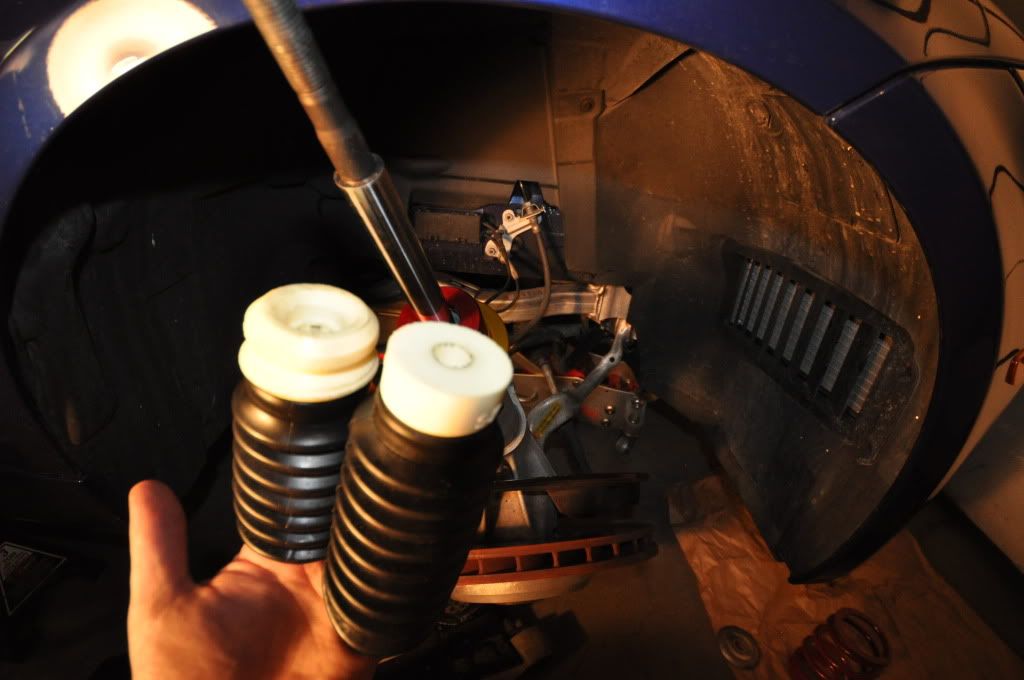
Damn. I'm so close. The kit included a couple new bump stops and I'm not sure which is for the front and which is for the back. My guess is the one on the left goes on the front but neither stop has a large enough inside diameter to slide down on the shock rod like the stock one does.

Image hosted on: i3.photobucket.com

I'm also hoping I can get a torque spec from GC on the link bracket nut. It seems to be a pretty soft metal, aluminum maybe, and I don't want to over torque it.
mact3333 wrote
Image hosted on: img189.imageshack.us
Also, you want to have the bracket-bolt assembly face the transmission -- and not the engine, like in this pic. Jay @ GC specifically instructed me to point the bracket at an angle towards the transmission in order to allow the sway links to work with the OE sway bar and now make noise.
mastek wrote
Also, you want to have the bracket-bolt assembly face the transmission -- and not the engine, like in this pic. Jay @ GC specifically instructed me to point the bracket at an angle towards the transmission in order to allow the sway links to work with the OE sway bar and now make noise.
WTF!...:)....Mastek, can you post some pics of your GC setup as I am taking my car in this friday for slight adjustment of height and would like to get this setup the right way.
I do remember Jay mentioning to mark the location of the bracket. I thought he meant mark it for height on the shock body but he must have been referring more to the angle the bracket points. Luckily I marked both. Your bracket doesn't look too far off if any. Has it made any noise?
mact3333 wrote
WTF!...:)....Mastek, can you post some pics of your GC setup as I am taking my car in this friday for slight adjustment of height and would like to get this setup the right way.
I will try to find the pics - but its simple really ...
- have the front of the car raised equally
- loosen the bolt on the strut clamp holding the sway bar link
- and spin the strut clamp towards the back of the car a little (Jay said to have the clamp pointing back at the transmission)
mact3333 wrote
does this pic help??


Image hosted on: img189.imageshack.us
I don't mean to pile on but I was just looking at this pic again and it looks like the bump stop may be on upside down. Stock, the boot is attached below the bump stop. I don't know how critical it is though.
SlamMan wrote
I don't mean to pile on but I was just looking at this pic again and it looks like the bump stop may be on upside down. Stock, the boot is attached below the bump stop. I don't know how critical it is though.
You are right, my bumpstop and sleeve is upside down.
Why don't these kits come with better instructions? :confused2

When I installed my Dinan springs it was the same way. Here are a bunch of parts; good luck figuring out their orientation. :rolleyes:
Better instructions would be nice for sure. I'm going to put together all the photos and notes I have for this for a DIY post.

I'm pretty much finished with the fronts. I just have to torque everything down to spec. It's taking so long since I only have a little time at night to work on it. I also don't have a 21mm-3/8in socket for my 3/8in torque wrench so I need to go buy an adapter or 21mm socket tonight. Balls! The back has to go faster.
Done with the front! Just need to knock out the backs tonight and set the ride height and sway bar links.
Well... how'd it go?