

S65B40 Rod Bearing DIY
Disclaimer
This DIY project is purely “at your own risk”. As with any DIY project, unfamiliarity with the tools and process can be dangerous. Posts should be construed as theoretical advice only.
If you are at all uncomfortable or inexperienced working on these projects (especially but not limited to electronics and mechanical), please reconsider doing the job yourself. It is very possible on any DIY project to damage your engine, vehicle, void your car's warranty, create a hazardous condition, or harm or even kill yourself or others.
The patient
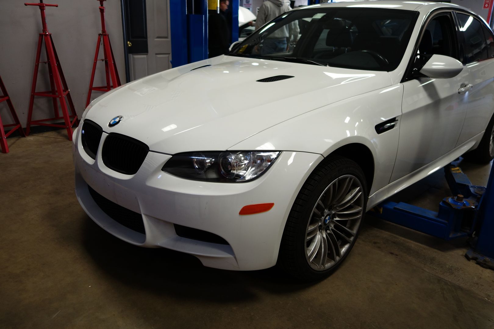
2011 E90 M3 DCT purchased with 36k miles a couple months ago. It is a stripper car with DCT as the sole option… in other words cloth seats, no nav, slicktop! It is destined for the track in the 2017 season. The first step is fixing the bearings!
Special tools used
3/8” 12 point socket to install the BE-ARP bolts
6 inch T30. I had a 4 inch one and it doesn’t work, so I lost an hour driving around looking for one. Do not start the work without one!
To remove the OEM rod bolts you can use a 12 point 12mm socket.
Special hardware used
BW street/track (Group N) engine mounts. If yours is a street car, I suggest replacing them with OEM items
BE Bearings. I don’t understand why anyone would use something else
BE-ARP bolts. Again, these should be the default choice for everyone. Besides being the best bolts for these engines, you do not want to be angle torqueing stuff in this tight a space. Somewhere, someone is thinking ‘$500 is a lot for bolts’. Well good luck with that...
Plastigauge. You need the green one. You can buy some at www.summitracing.com/search/product-line/clevite-77-plastigage
Two different Computorq3 electronic torque wrenches. I have the ½” one as well as the ¼”, which covers the range of required torque. To do this with a crappy/inaccurate torque wrench is a waste of time.
Harbor Freight Engine hoist. I used this on my E46M3 rod bearing DIY. It’s a cheap piece of hardware that works exactly as designed!
Snap-on 3/8 electric ratchet. This makes everything a lot easier. There are a TON of bolts you have to remove to do this job, I highly suggest either this or the Milwaukee one
Time taken
This took 12h, first time doing it. We usually are slow workers. It was 10h one day and 2h the next. There is no doubt that if we were not doing a DIY - which requires you to spend lots of time pausing to take pictures, etc and renders one of the two people working useless - it would have taken significantly less. There was also one snag with the 4” T30 and subsequent easter egg hunt which took time, but you get the idea.
Torque specs (courtesy of E92love)
oil pan bolts (30 qt) and all other M6 bolts inside/outside engine: 10 Nm
steering rack bolt on step 6 (1 qt) (M8): 21 Nm
E12 transmission to oil pan bolts (4 qt) (M10): 38 Nm
engine mount nuts. 1 top, 1 bottom on each side: 56 Nm
the 6 front subframe bolts (M12): 108 Nm
rear 2 most subframe bolts (M10): 56 Nm + 90 degree
re-enforcement plate bolts (7 qt) (M10): 56 Nm + 90 degree
4 water pump pulley bolts (M6): 10 Nm
pulley tensioning system on both sides. 2 for each side (M8): 19 Nm
Part numbers (courtesy of ///Mobbin)
---bolded part = essential---
11137841085 - e92 m3 oil pan gasket
Oil pickup tube/system parts that I also ordered (just in case):
11417839832 - pickup tube o-ring
11417839833 - pickup tube o-ring
11417838534 - suction pipe gasket
11427837997 - oil filter kit (oil filter, o-rings, crush washers)
07119904550 x 2 - oil pan drain plug (includes crush washer also)
07-12-9-905-537 - 16 x oil pan screws
07-12-9-905-599 - 12 x oil pan screws
07-12-9-905-600 - 2 x oil pan screws
12611744292 - oil level sensor o-ring
11812283798 - engine mounts (might include nuts, not sure)
07119904025 x 4 - engine mount nuts
Acknowledgements
Kurt, Philip, Ryan, Bert&Ernie from BE Bearings. You can self-identify if you wish, but I sincerely appreciate your openness to being contacted for issues as well as the technical help from Bert&Ernie
Special mention to GearHeads International – which is paradise for the motor enthusiast! As many of you probably know, I no longer have a lift (or heated garage, for that matter) so in the northeast winters my capacity to do more complex DIY’s has seen itself a bit hampered… so I’ve been limiting myself to doing work on the cars outdoors. Well, no more!
For $150 a day, GearHeads in RI will rent you a climate-controlled bay with a lift and all the SnapOn & GearWrench tools known to mankind. It is such an impressive place! Ron, the owner, is always there (yes, 7 days a week) and is really nice. I am sure I’ll be back!
Ron is a mechanic and he swings by to see how you’re doing and is always willing to lend you a hand. I could not have been more impressed!
GearHeads allows you to live in an apartment and still access tools and a garage to install your suspension, supercharger, rod bearings, all those critical projects. You no longer have any excuses!
Note 1
As you will drain the oil you will need to refill it. A typical oil change in this car is 8 quarts/liters and a little more. While changing rod bearings you remove a massive amount of oil which would typically never leave the engine, which means you will need 9.5 bottles to fill it back up so the car is happy. Protip: have more than that just in case!
Note 2
At times the DIY pics will show something I haven’t explained yet, so it may seem out of order. That is because at times you try different things. You should follow the order of instructions explained here
Note 3
Rod bearings do not require break in. If you used assembly lube, you should change the oil after a few thousand miles. Both BE Bearings and Bimmerworld were contacted to weigh in on this. When you think of it, a rod bearing should never have contact with the crank. Regular break in is more about seating the rings and walls than anything else
Note 4
If you have a Dinan underpulley set you'll need to rotate the engine through the alternator. It can be done counterclockwise.
The patient
Putting the DCT into neutral. The 6MT guys can skip this part
Lift the shift boot from the front by pressing rearwards and unclipping it
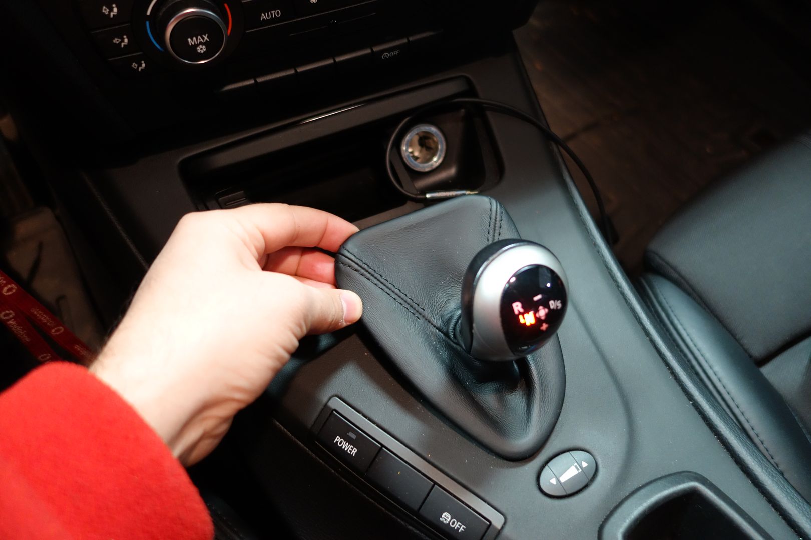
There is a black guard which you can see in this pic. With a screwdriver, move to forward and it will slide out of the way
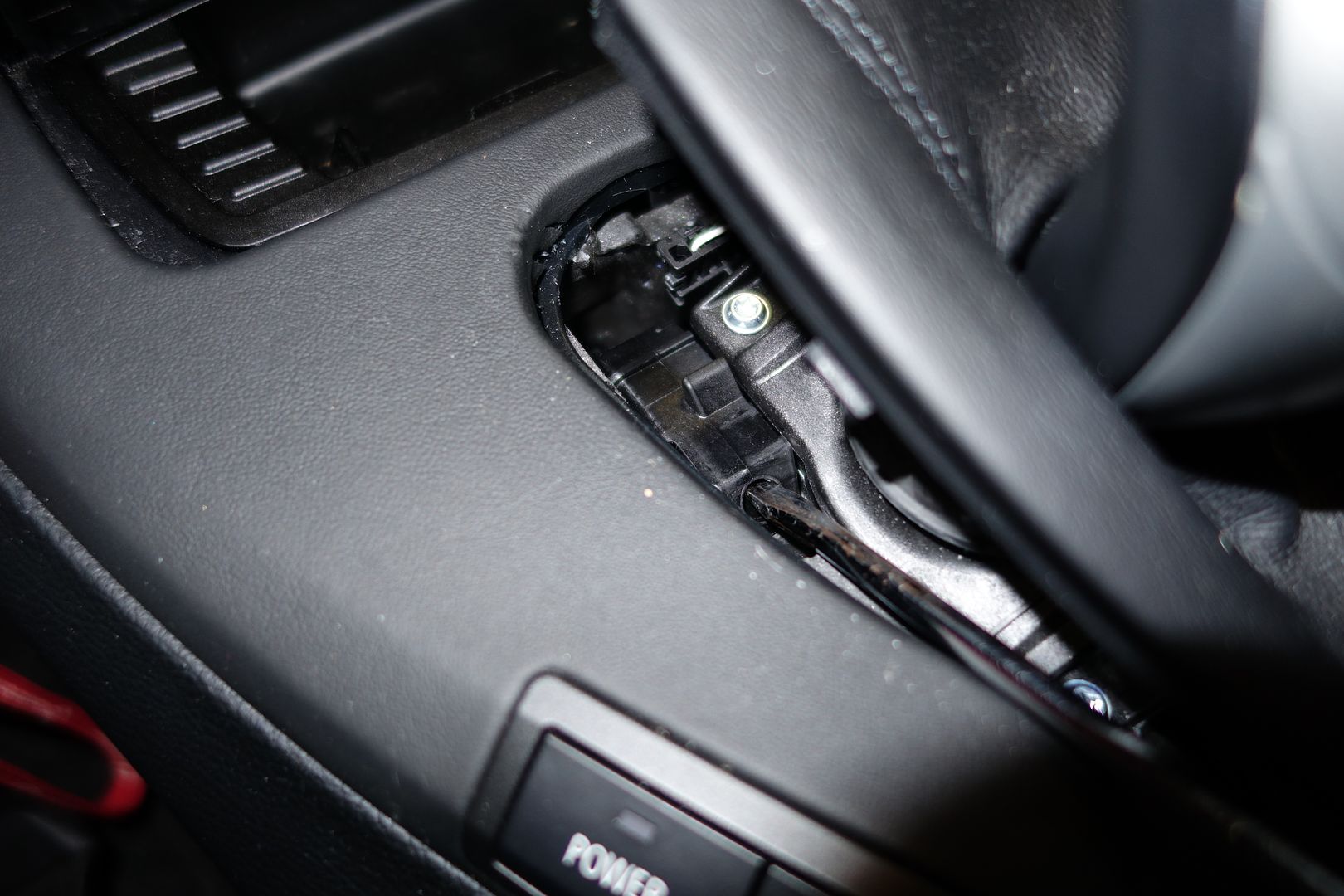
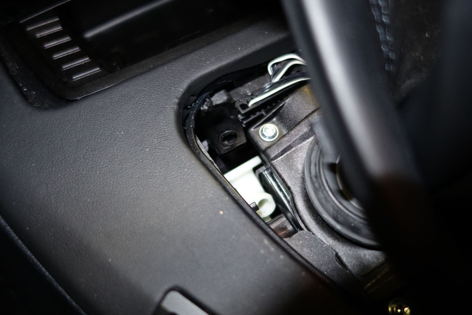
Here you can see the white lever that hides behind the black guard. You put a screwdriver in there and move it. The car will go into neutral and you'll hear a dong complaiingn about it
Install your engine support brace. Here are some pics of mine. You need to slightly tension it ‘upwards’ so that it is trying to pull the engine up, just a little bit. Remember the engine mounts are still installed so the engine cannot move much


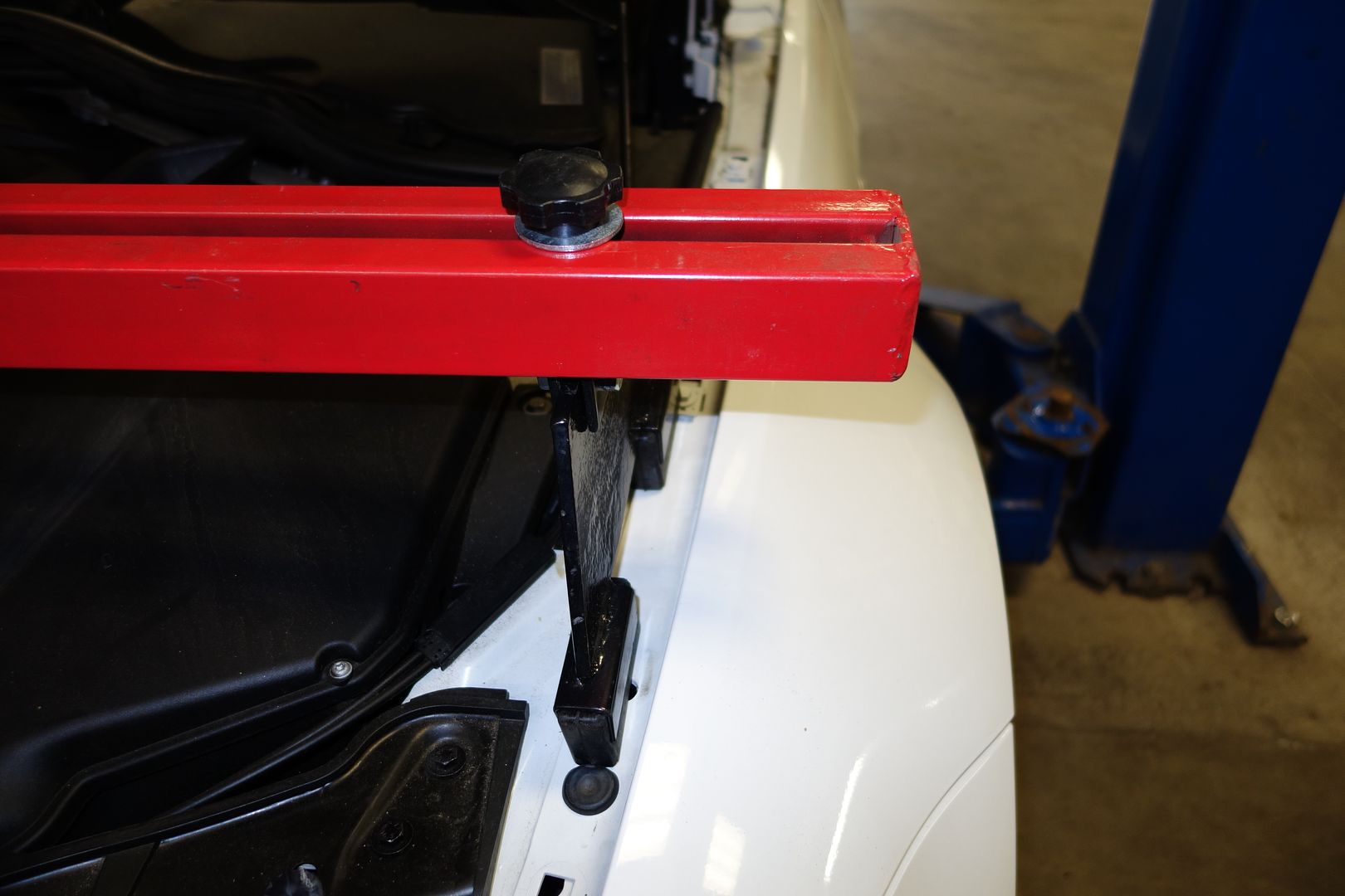
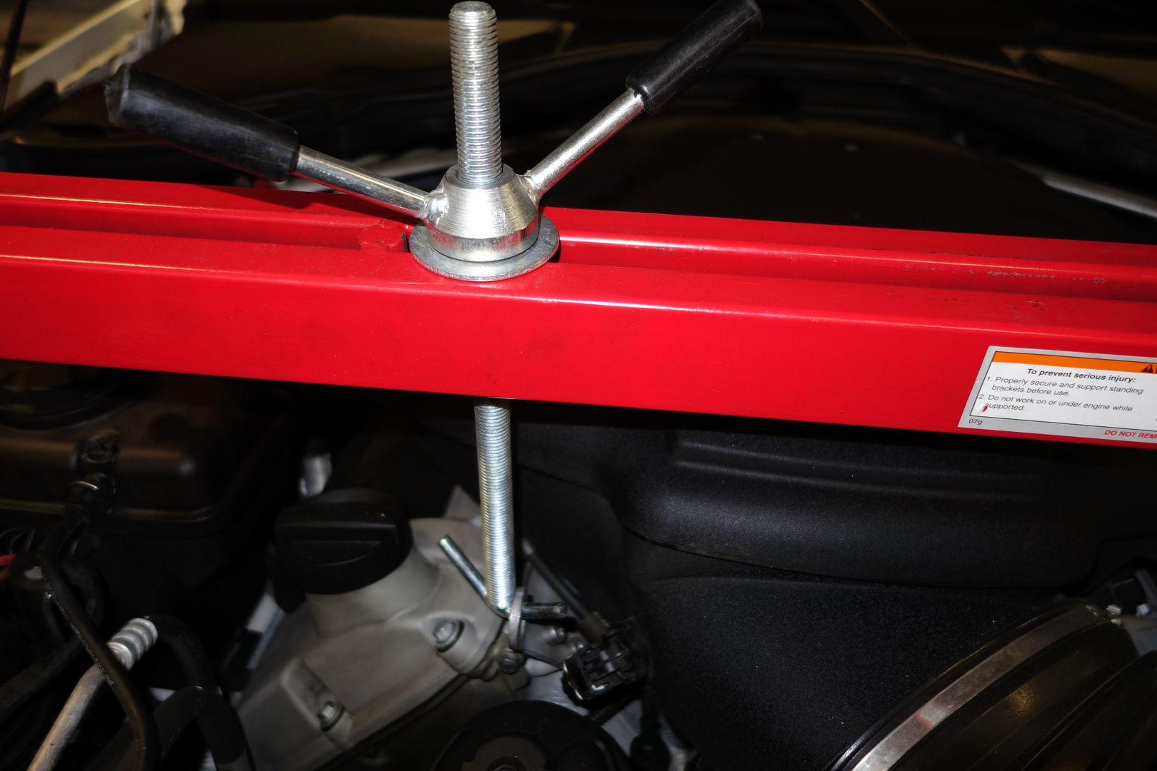
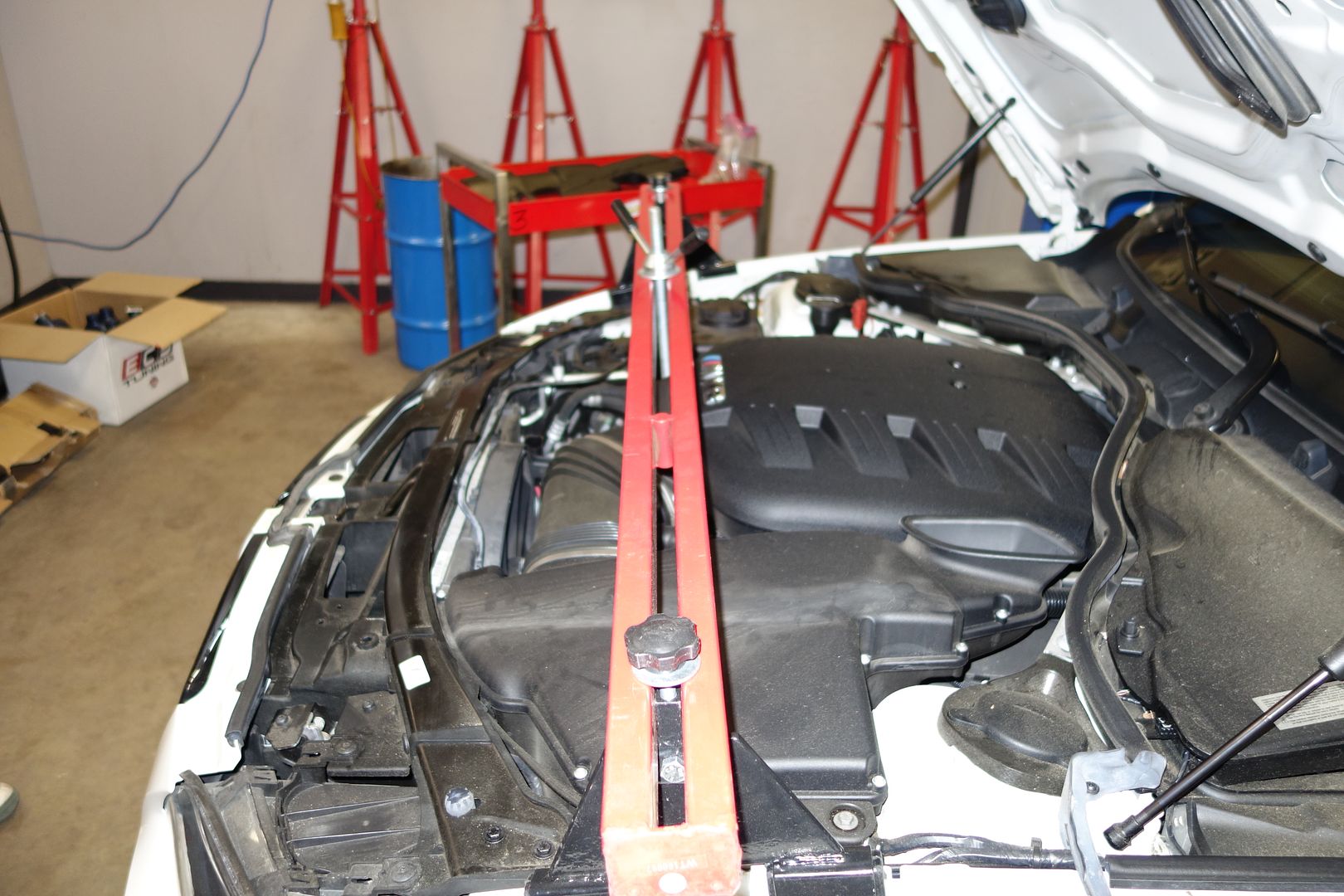
I try to minimize potential energy, so I put a cushioned mat on top of the sharp parts of the engine support bar and then rest the hood on it

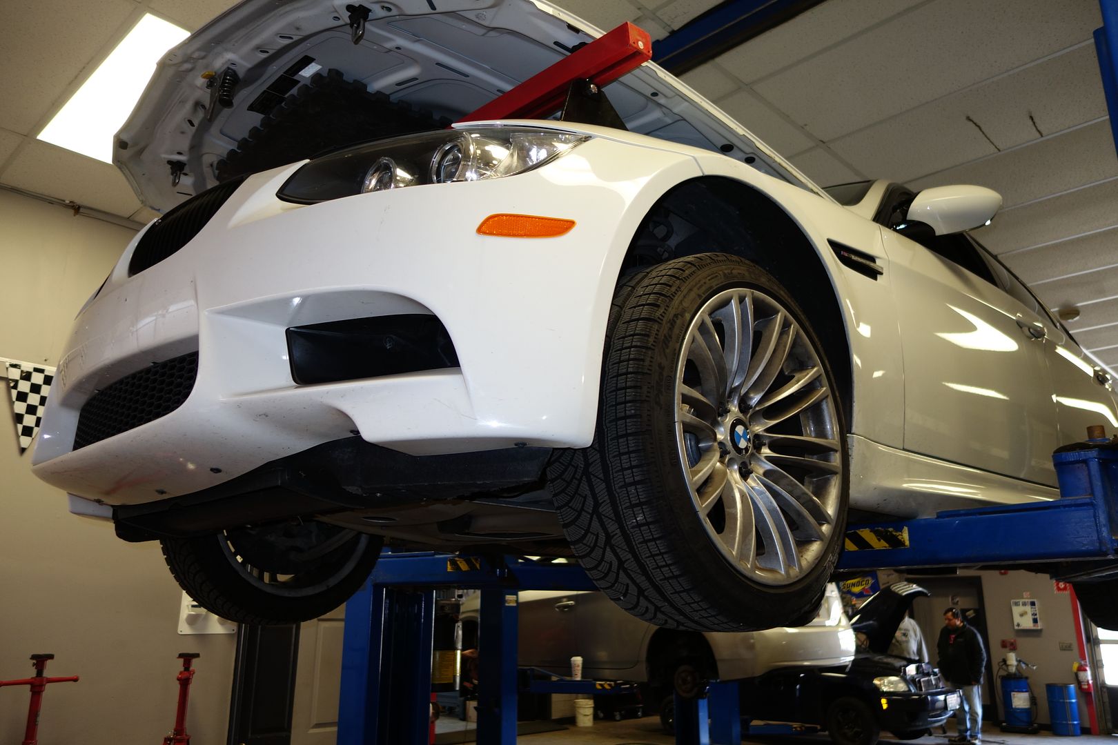
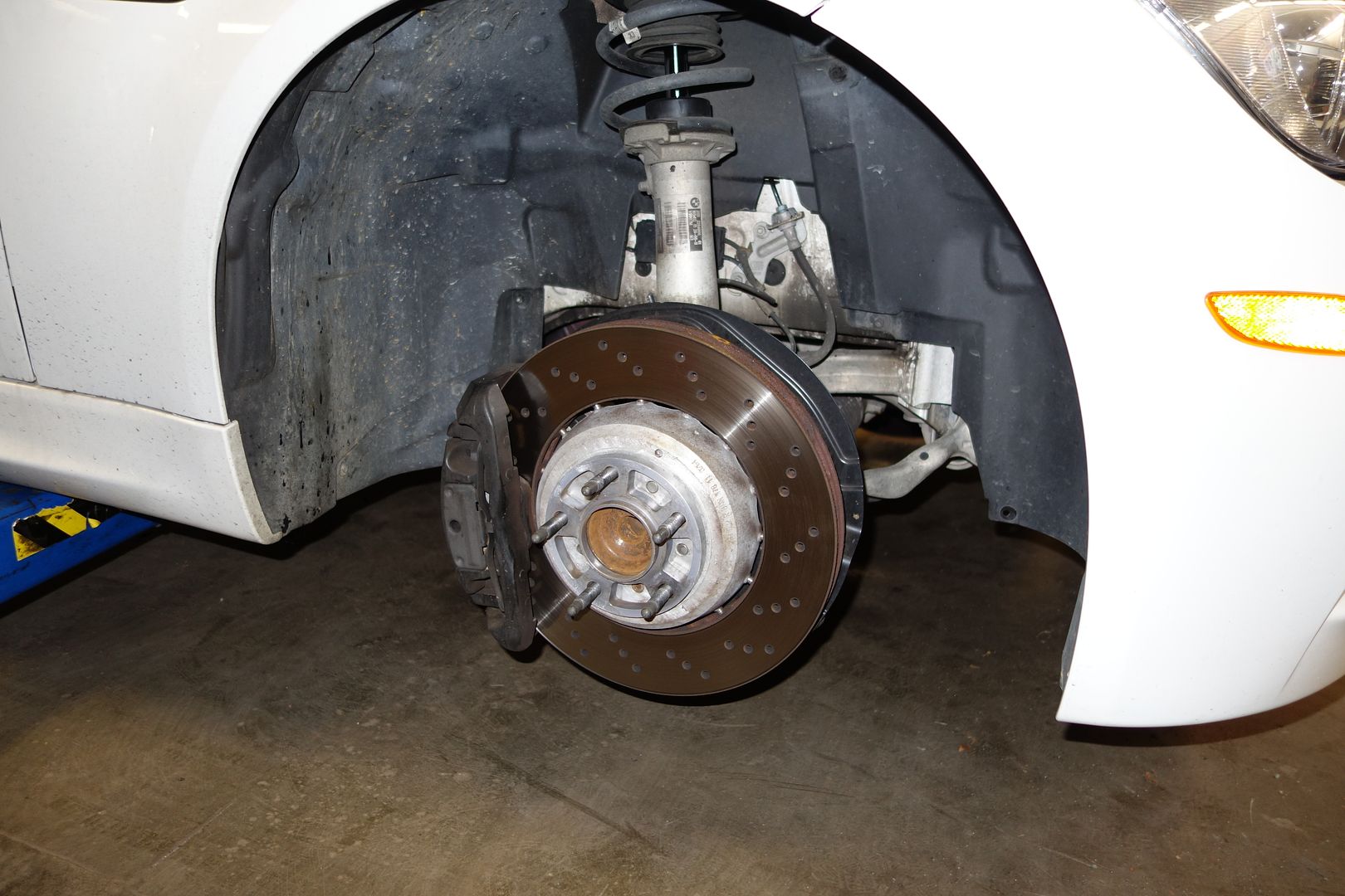
Remove the front wheels

We remove all the black felt underbody panels. There are many, many little screws
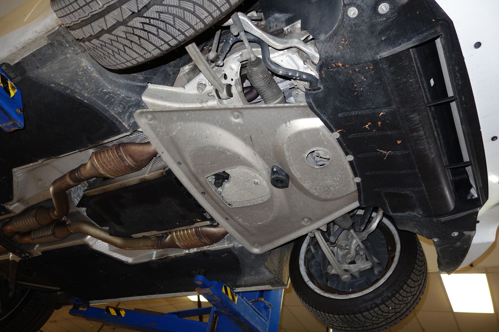
Note the three rear ones of the front felt part are different than the rest
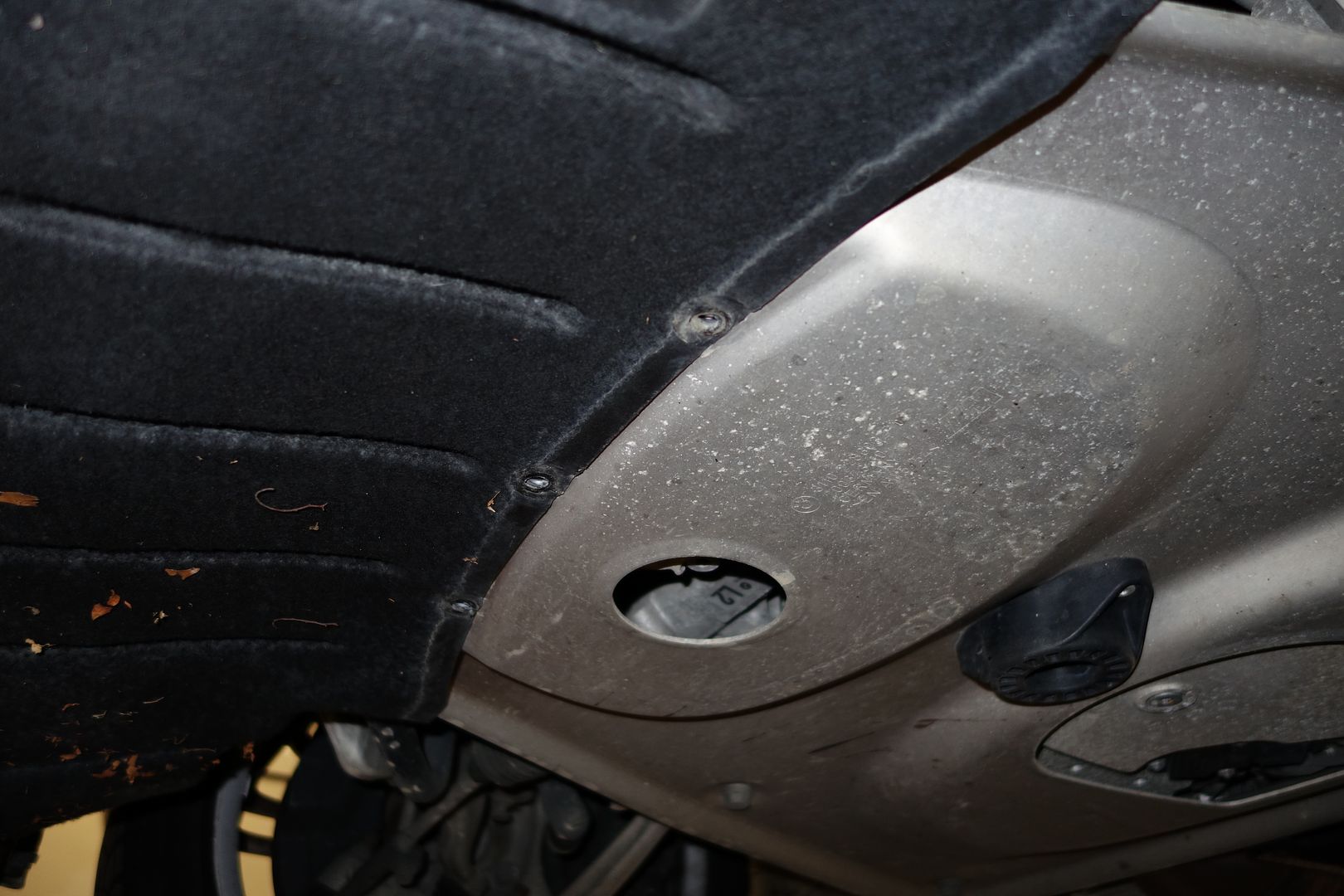
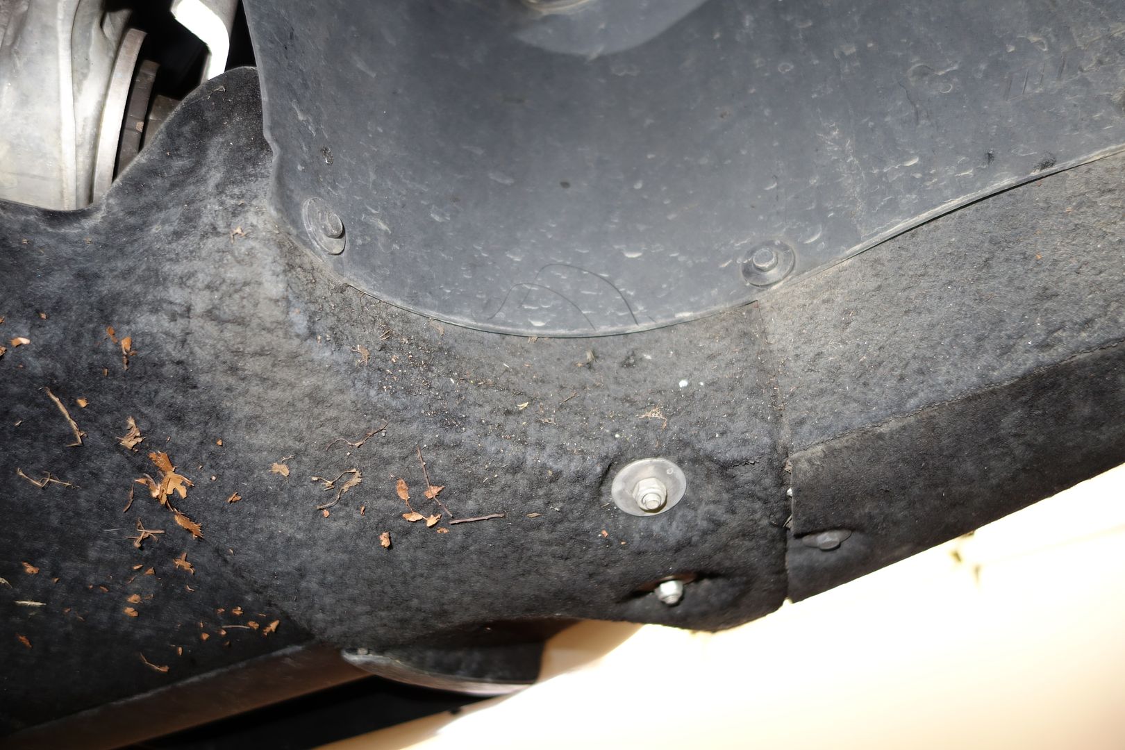
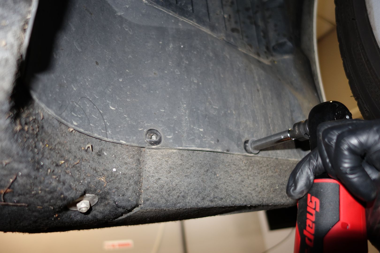
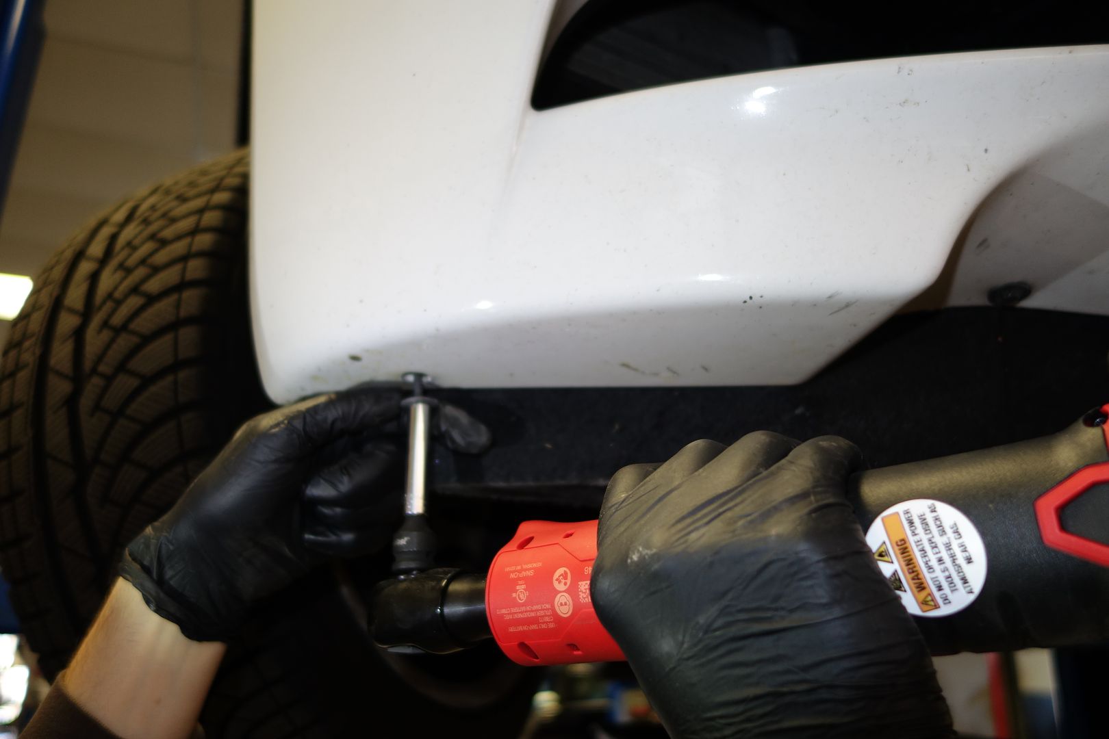
When you remove the side front ‘wings’ you can see the cable structure that supports the front felt part. You slide the top sideways and then out so it falls freely. Note you don't need to remove the two screws that hold the bottom of those cables.
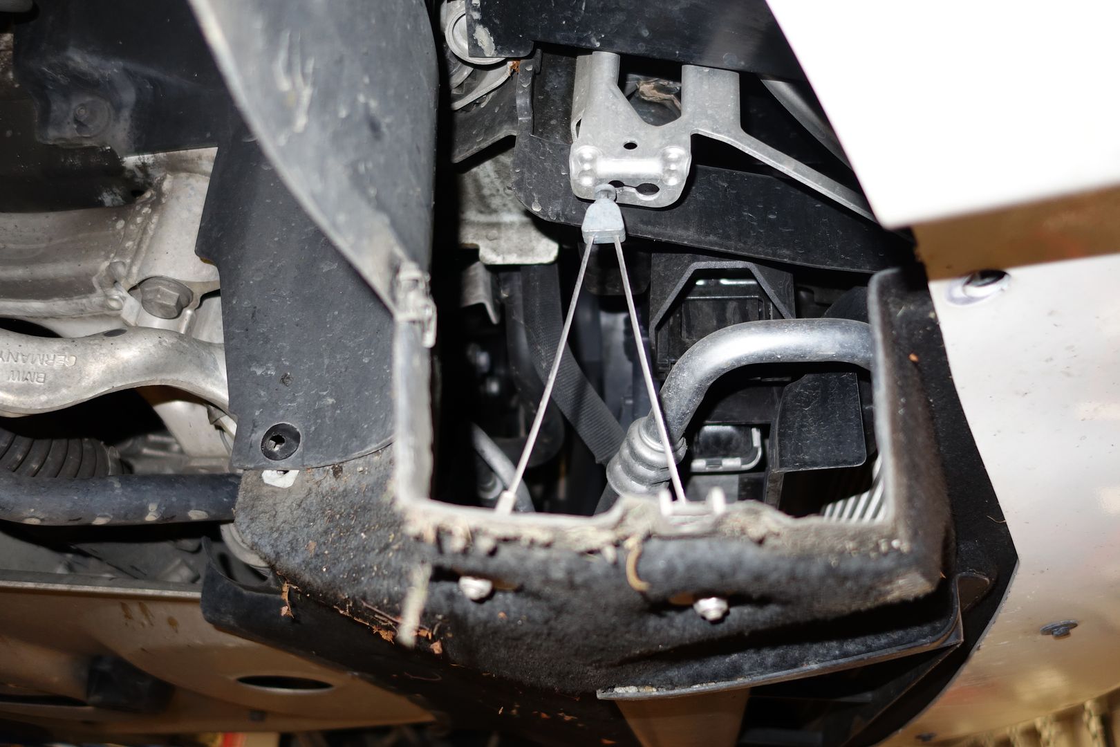
Continue removing the bottom felt pieces

More felt pieces
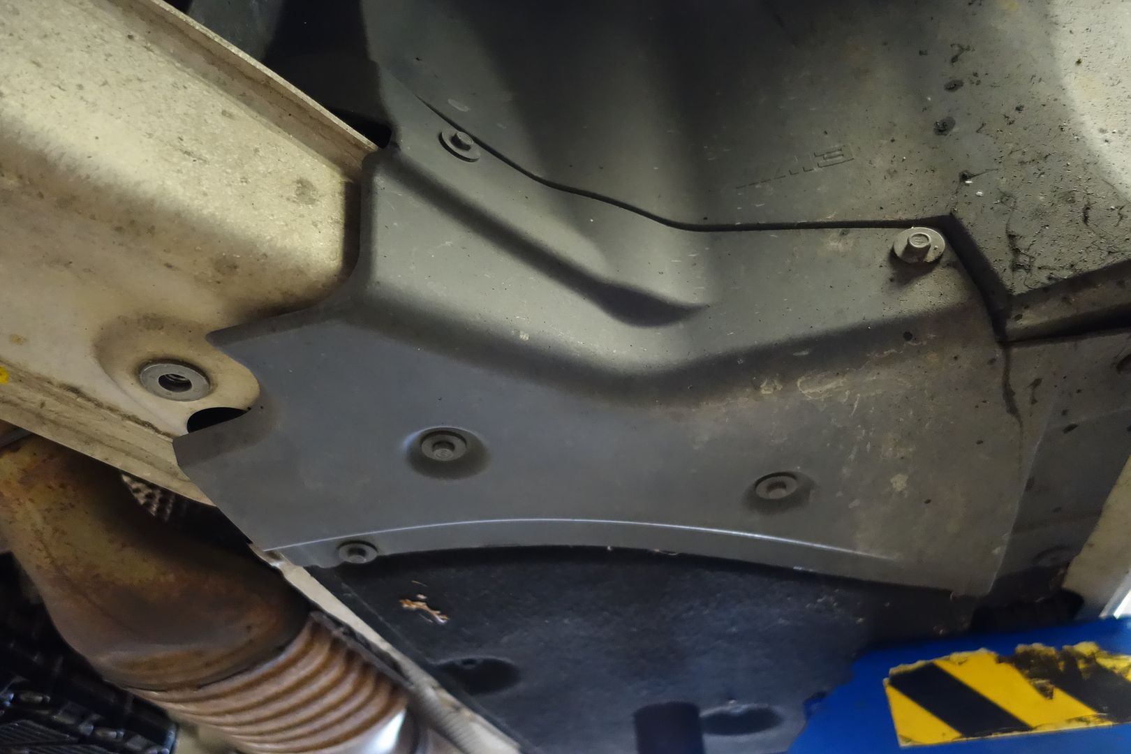
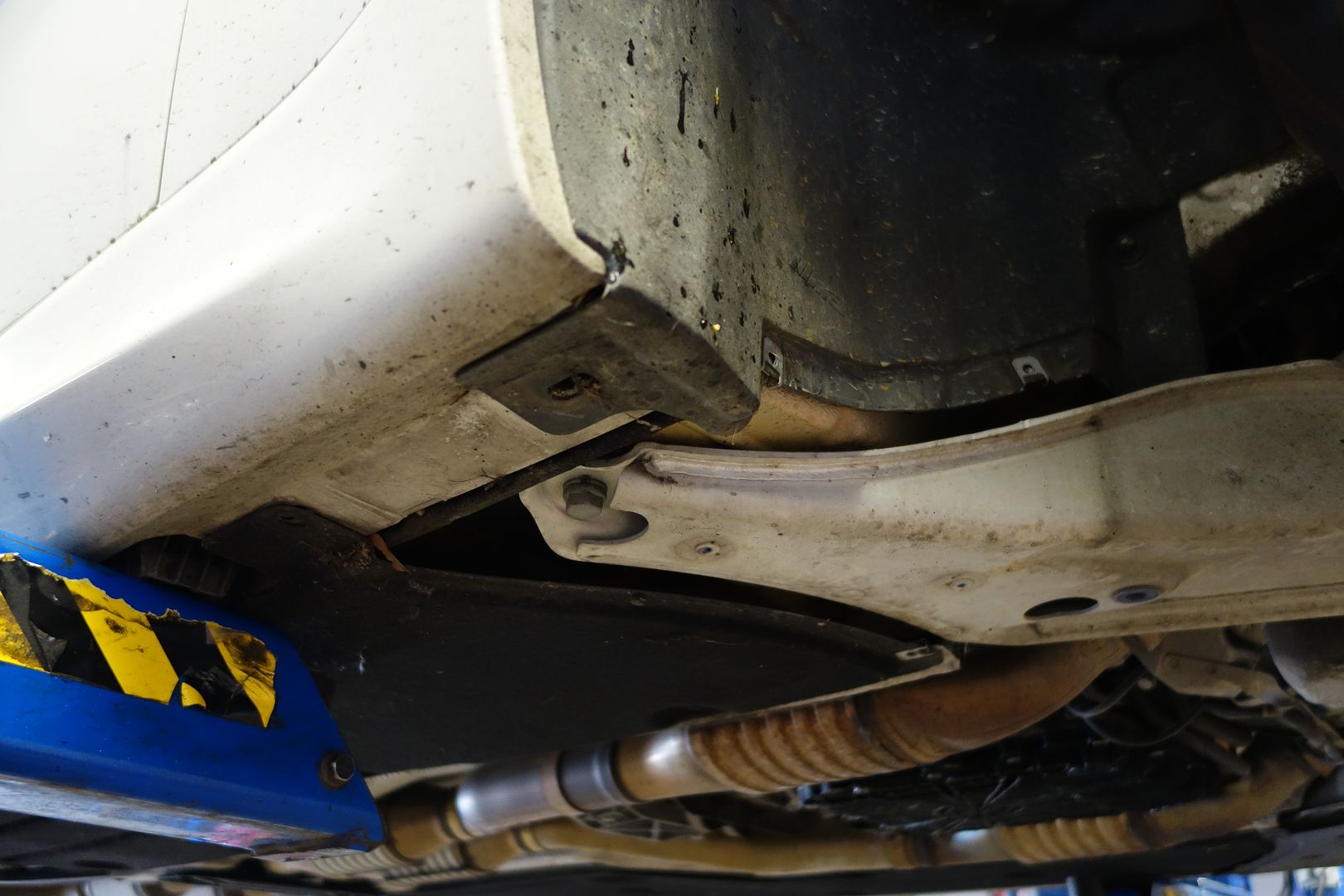
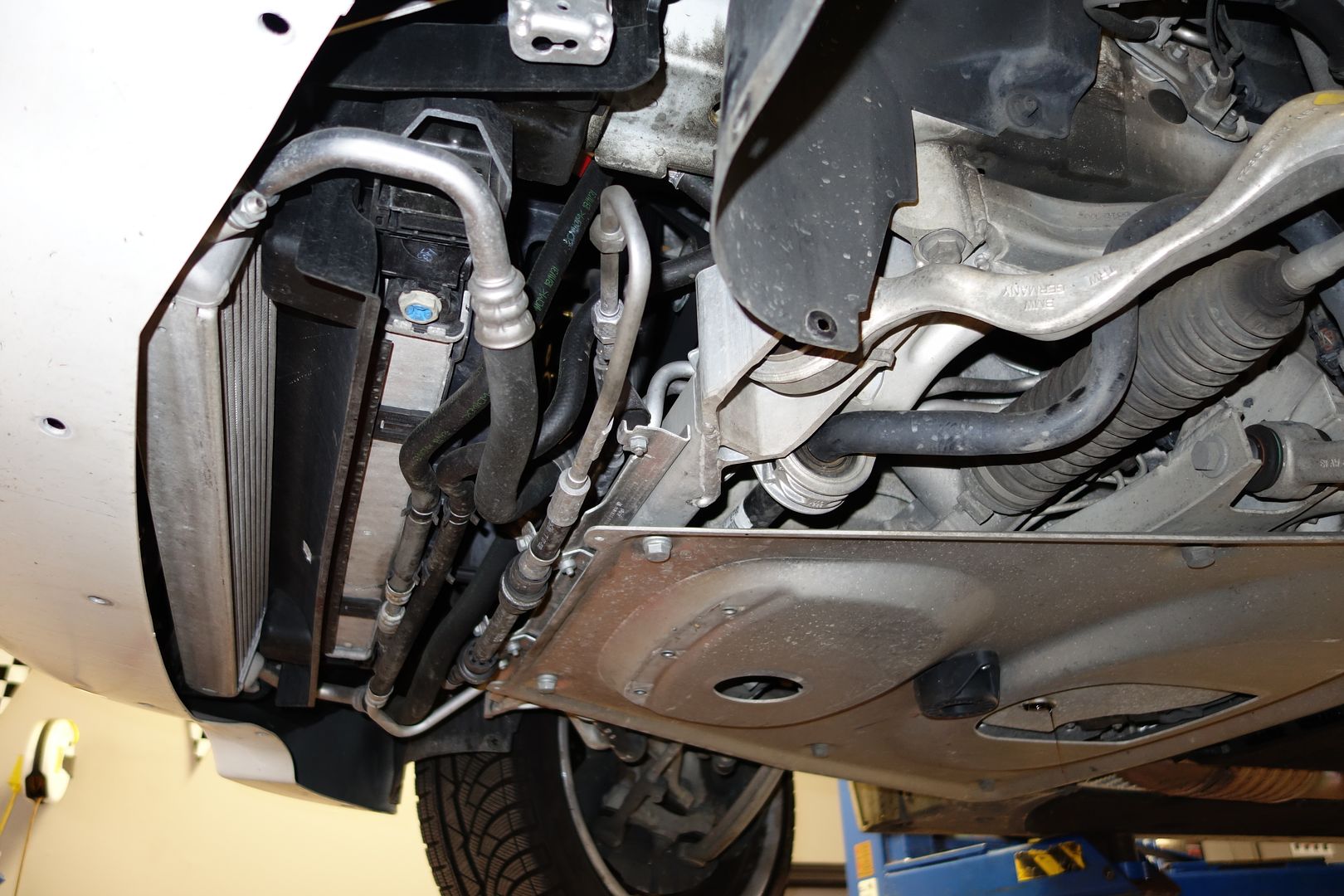
This is what you’re left with. Note the clips on the bottom of the fan which hold piping. Remove all the pipes from the clips
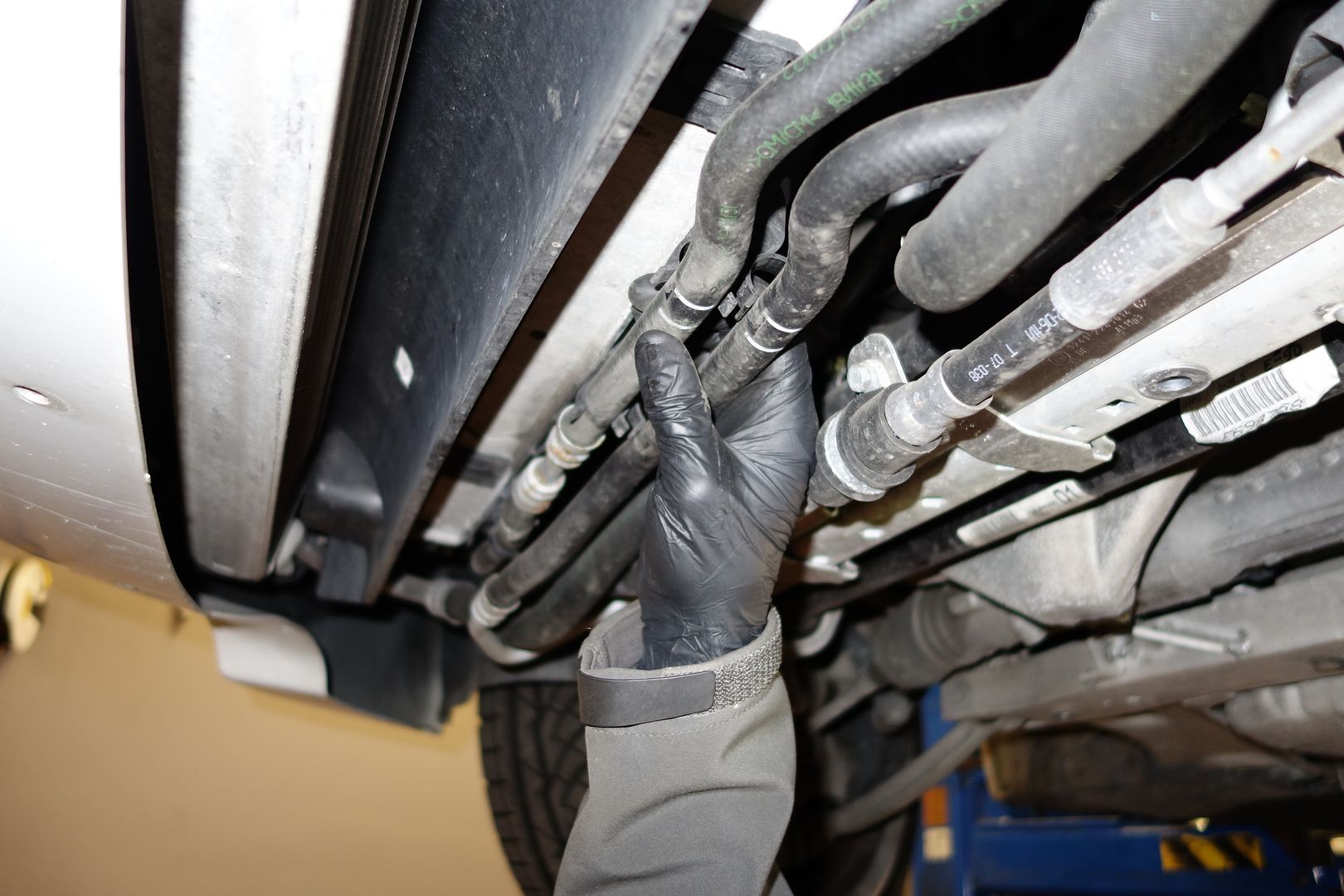
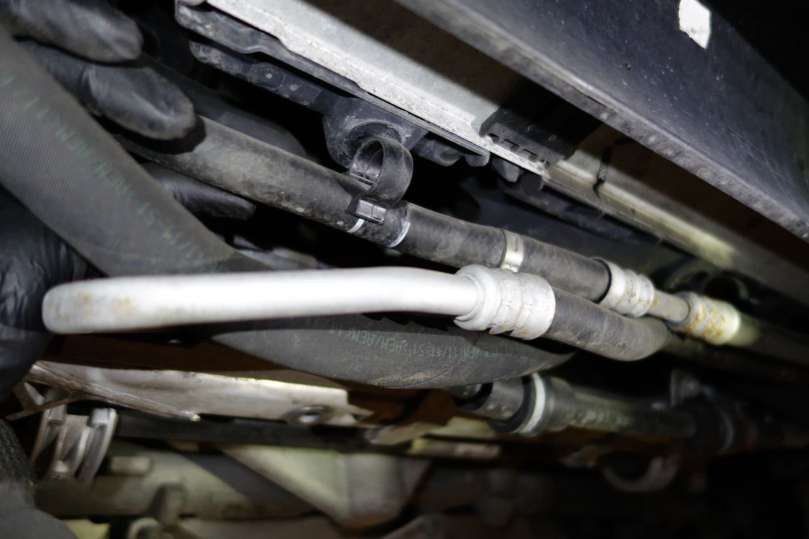 2
2
Remove the aluminum chassis brace. There are 7 bolts, one of them is conveniently hidden inside the front center jack support
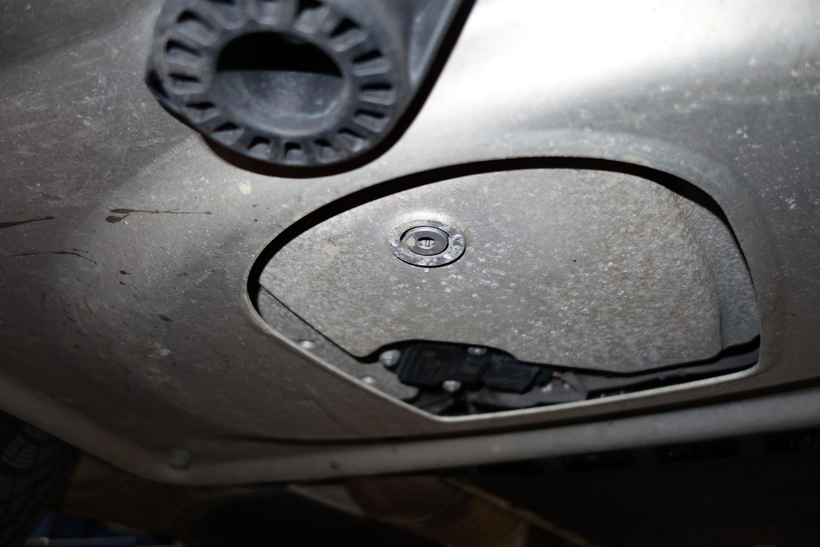
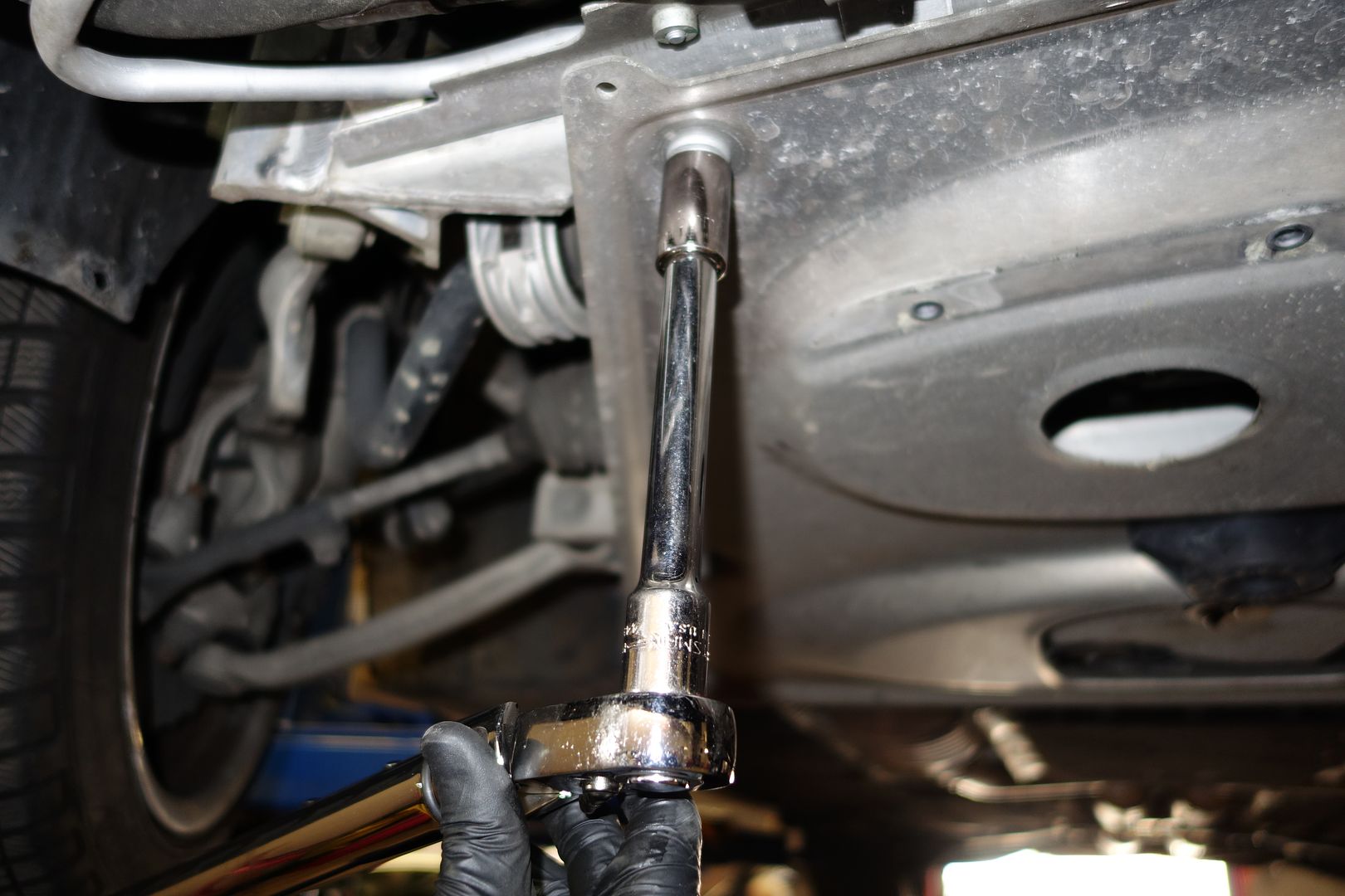
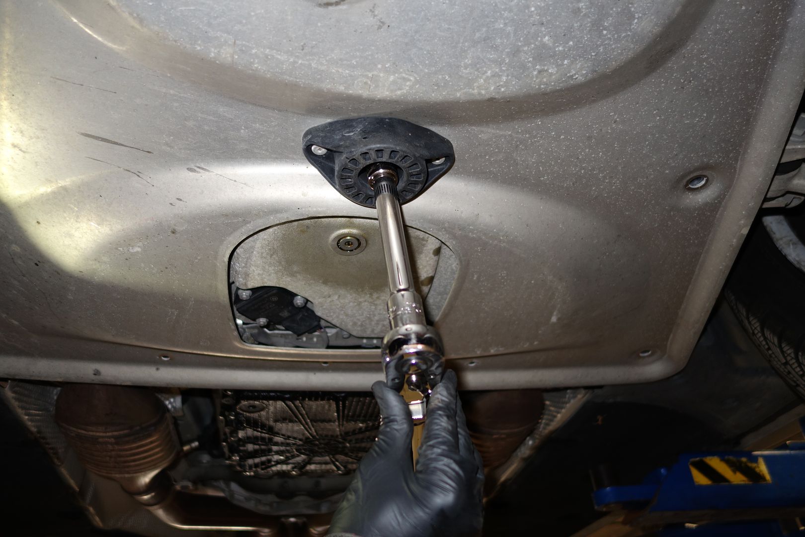
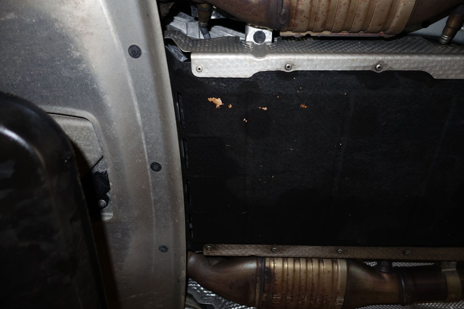
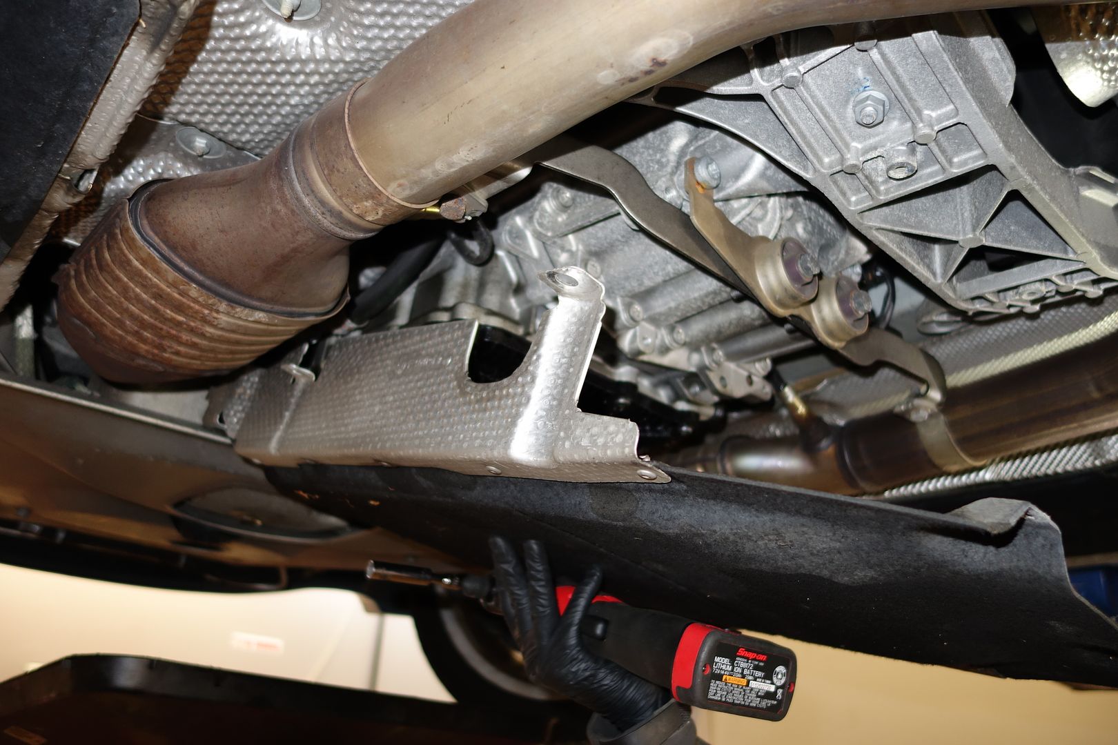
Remove the tranny felt underbody
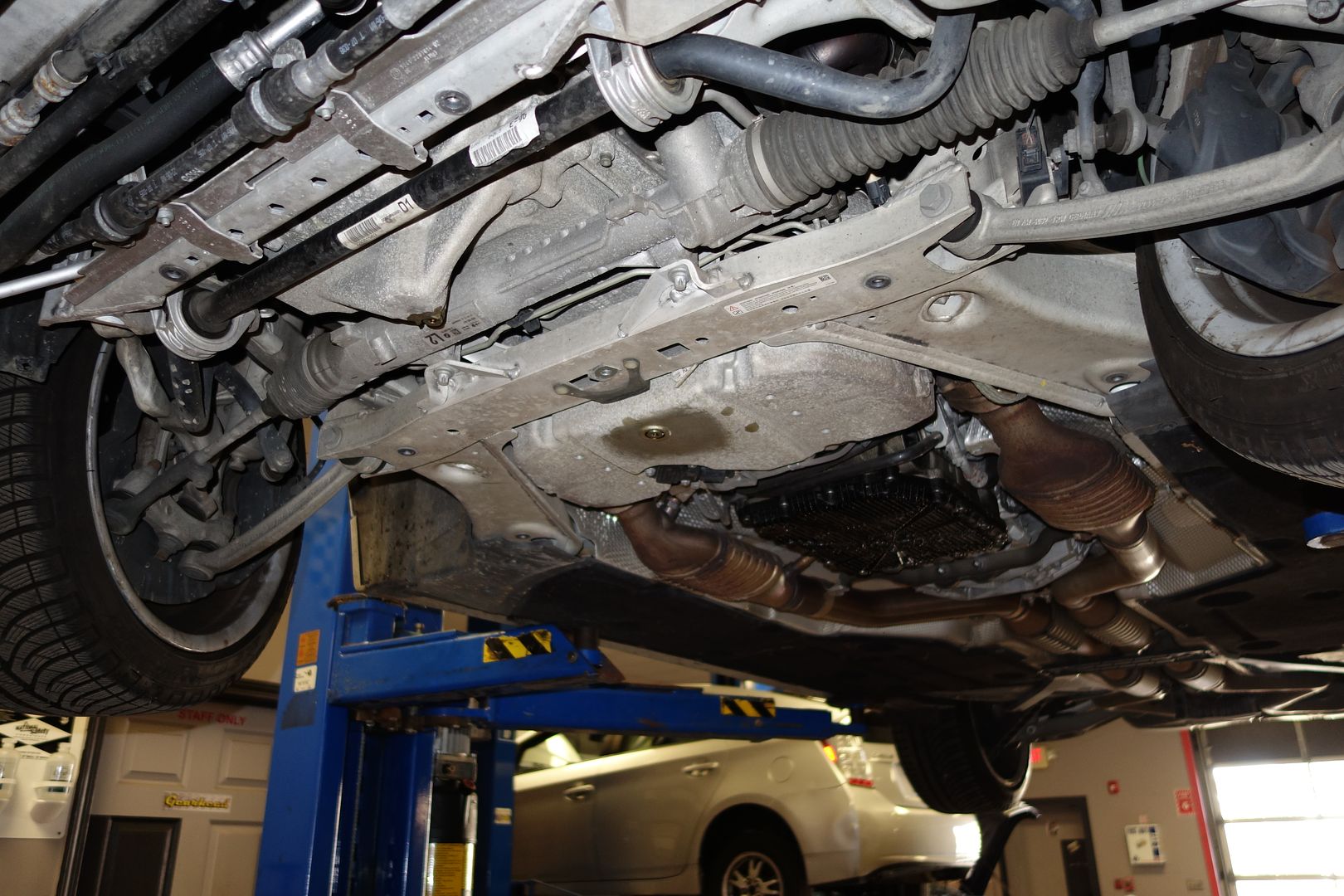
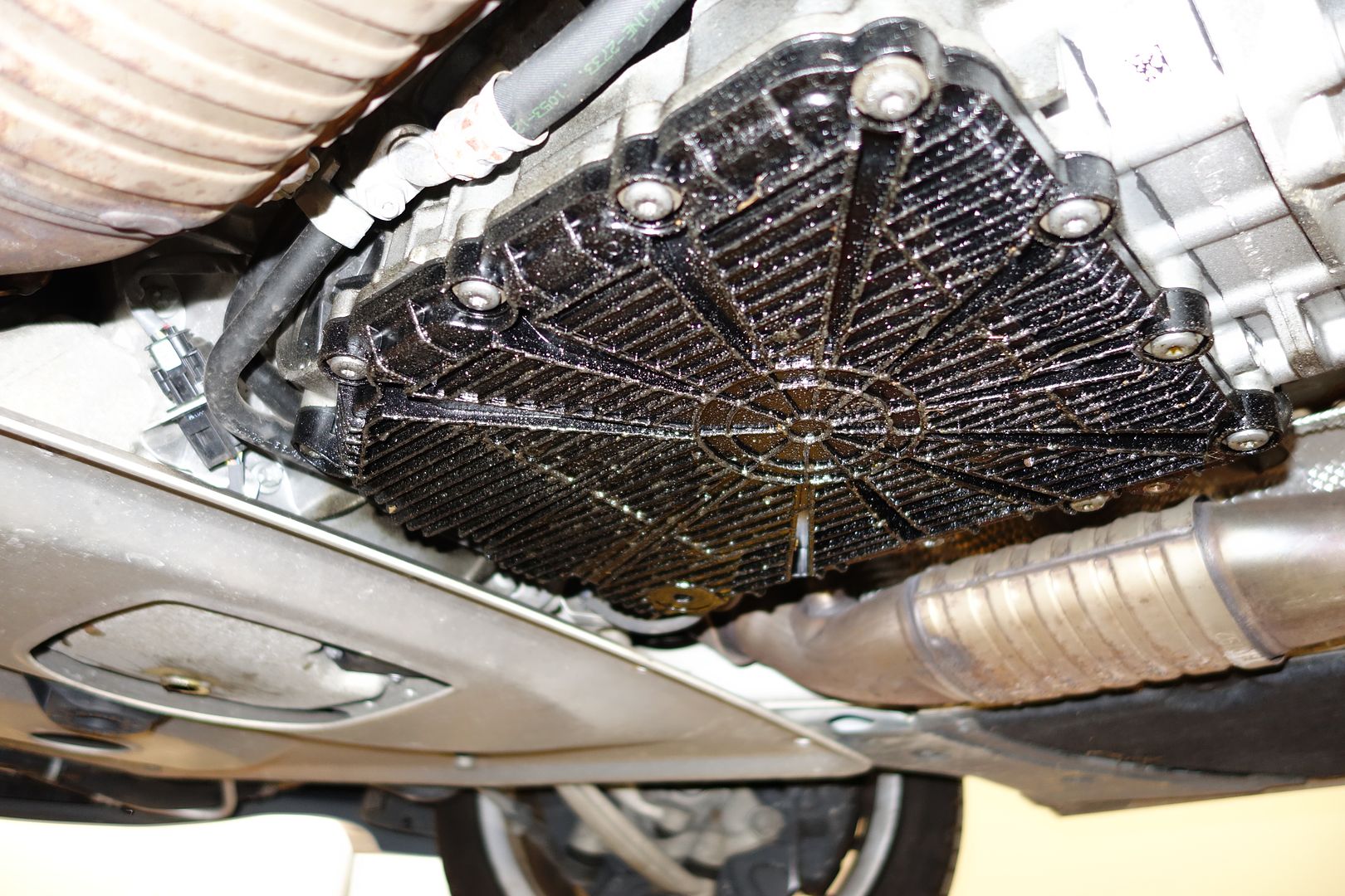
A leaky DCT pan… wonderful… I’ll get to that sucker late[EDIT: replaced with Slonik/Slon Workshop DCT pan, incredible part!]
Go back to the top of the car
We now move onto the fan. I did the removal and reinstallation without removing any more of the air intake. It’s easier if you remove the air box, but it can be done like this
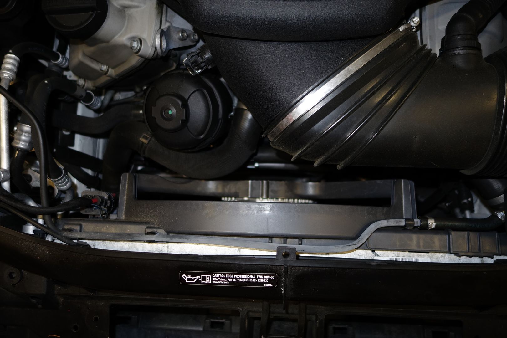
The radiator is held on by a single torx bolt on the passenger side. You can see it here. Remove it
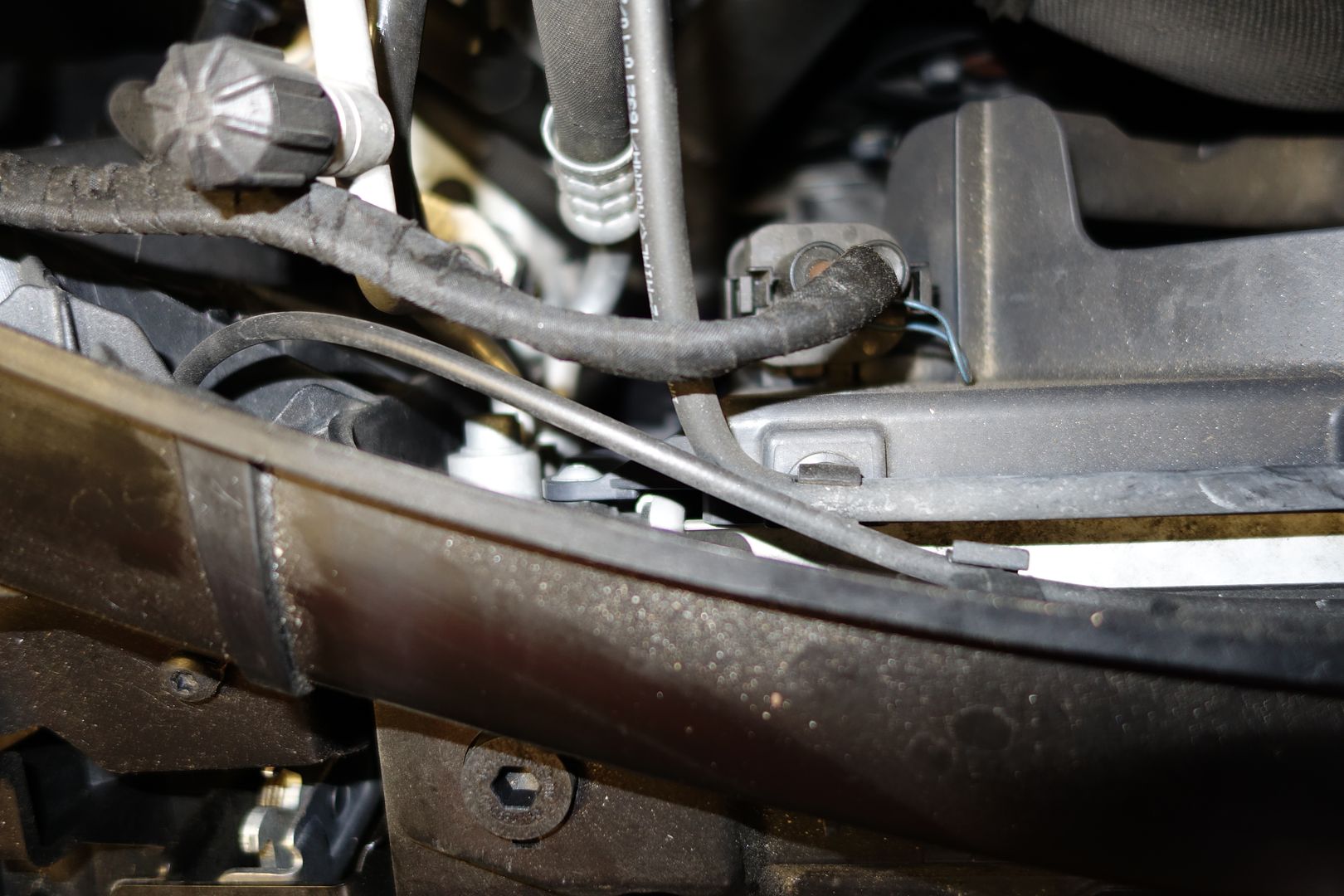
Unclip the large connector right by the torx bolt
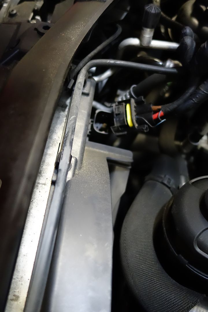
You can try sliding the fan upwards but it faces resistance. This is because there’s a clip that has to be undone on the driver side and the bottom of the fan has pipes clipped onto it
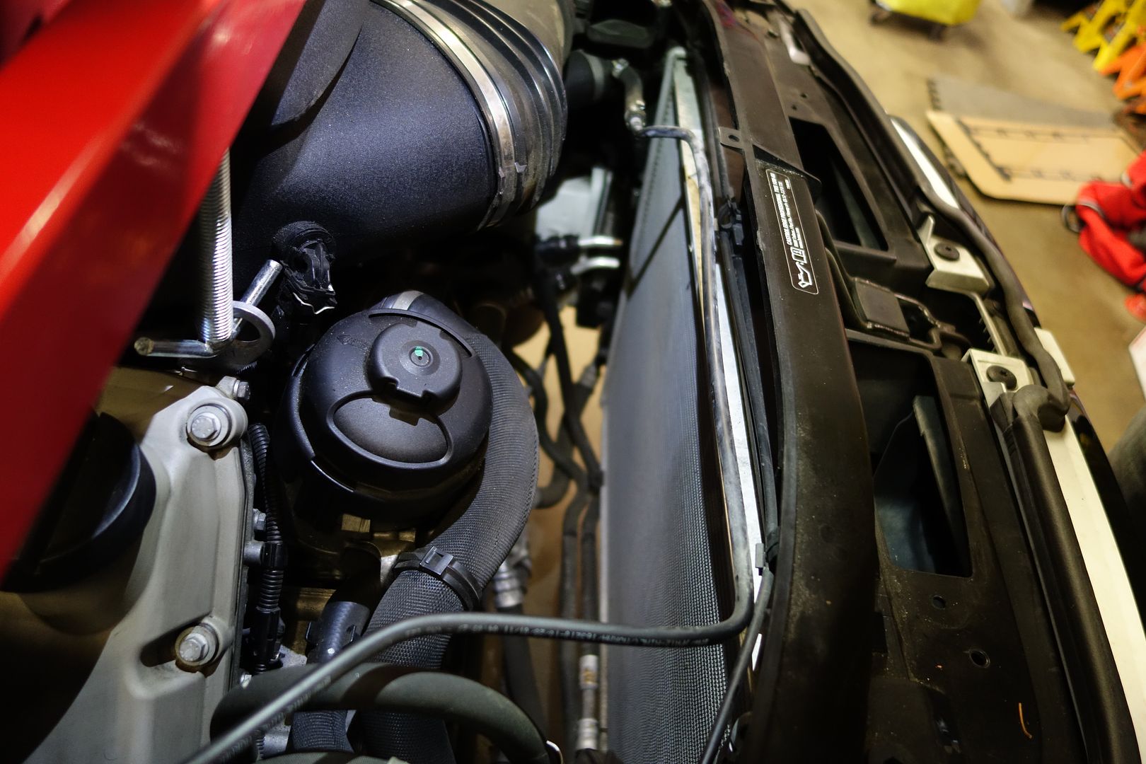
Lets go for the clip on the driver side, on the edge of the fan. You can just about put your arm in there and unclip it while you move the fan up. It’s a really tight, PITA fit but eventually you will release the whole fan after a lot of wiggling.
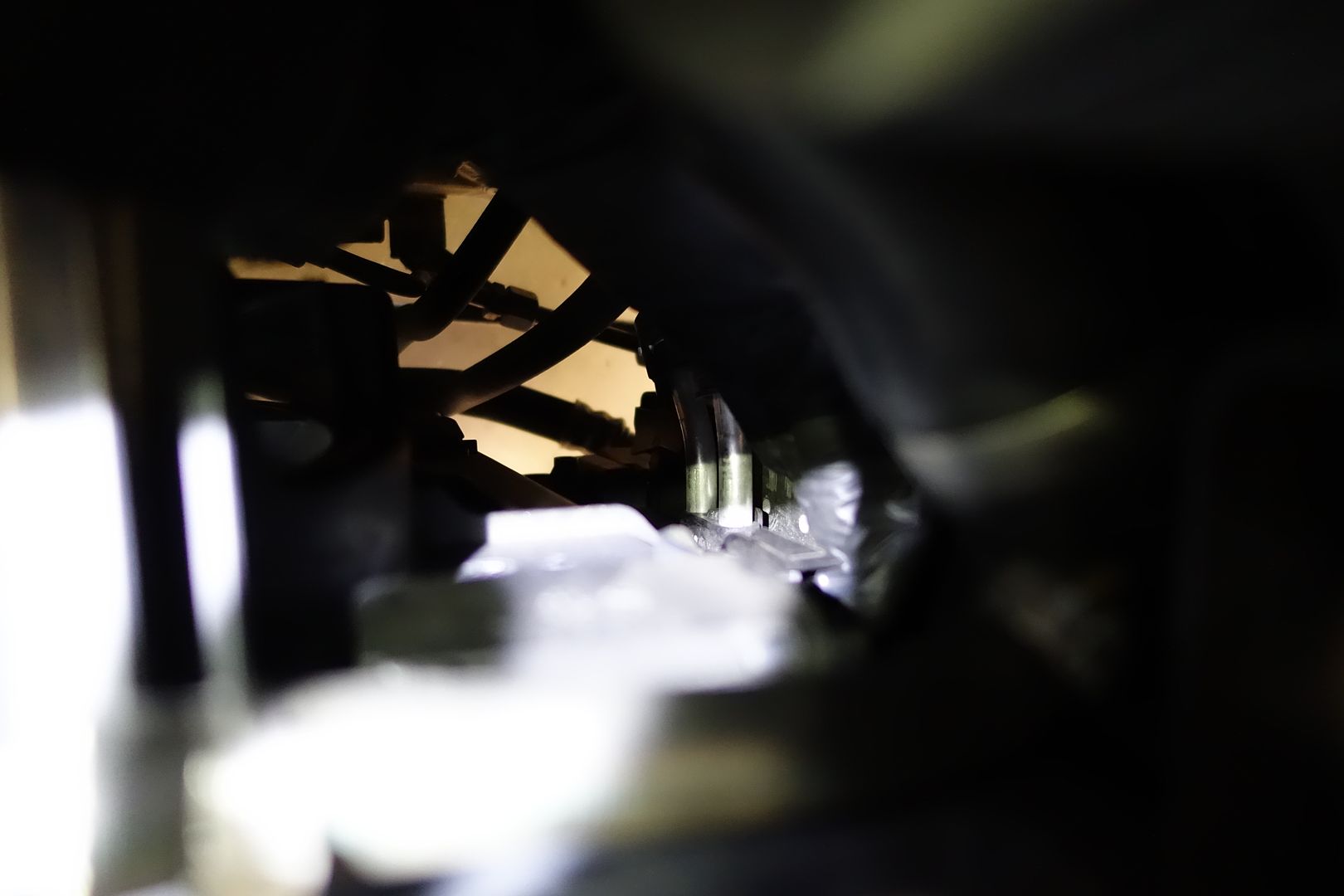
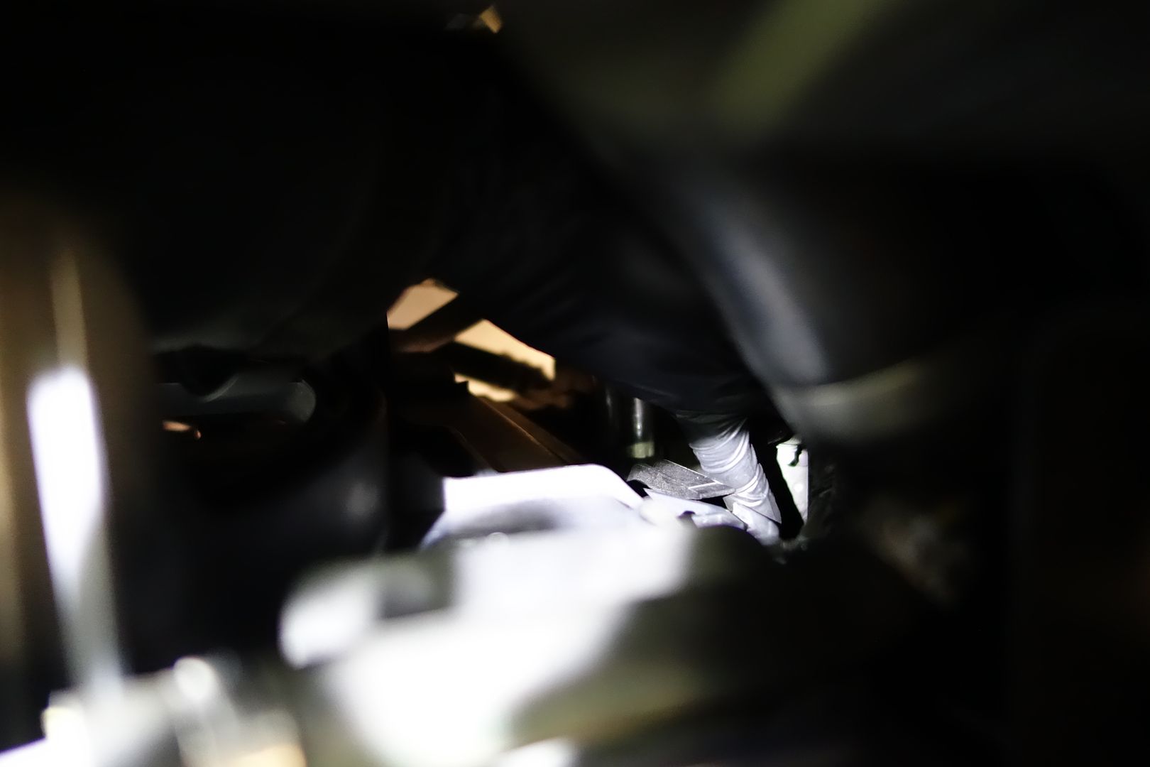
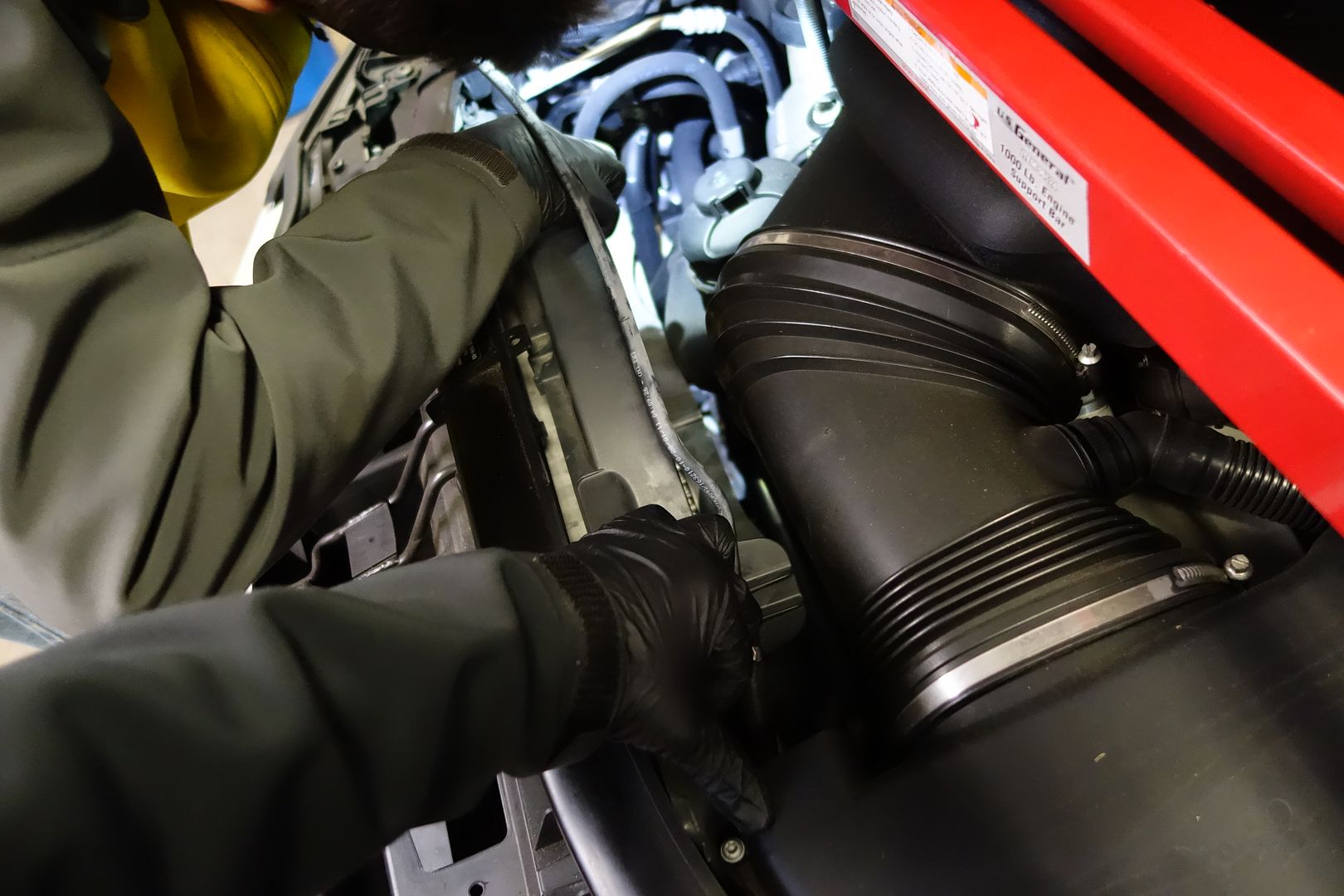
Peekaboo
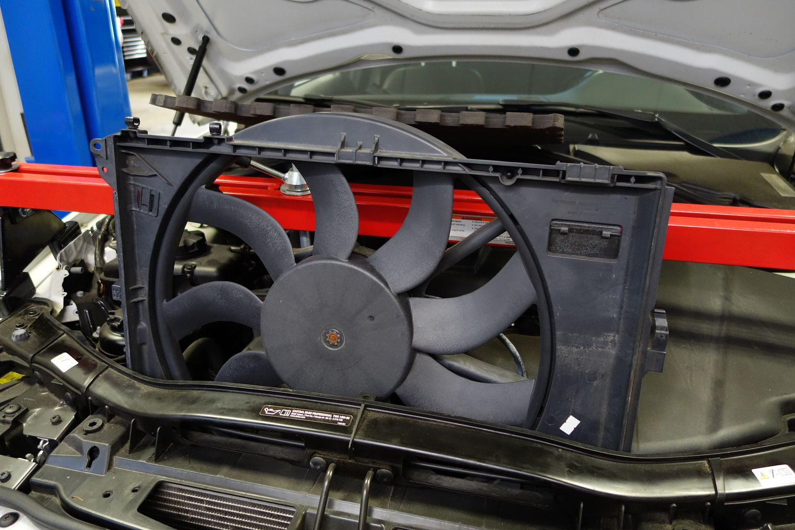
Finally
Go back to the bottom of the car
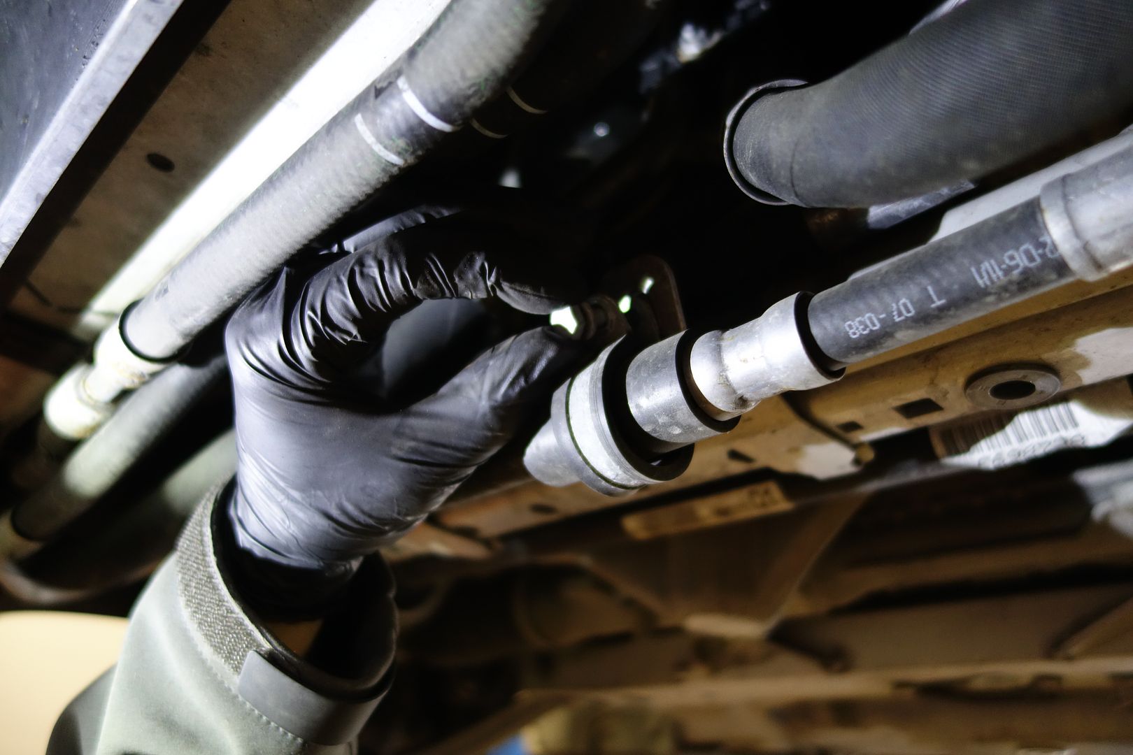
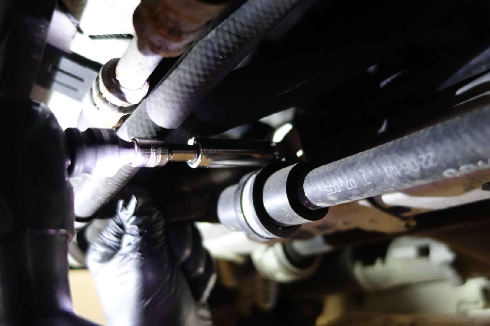
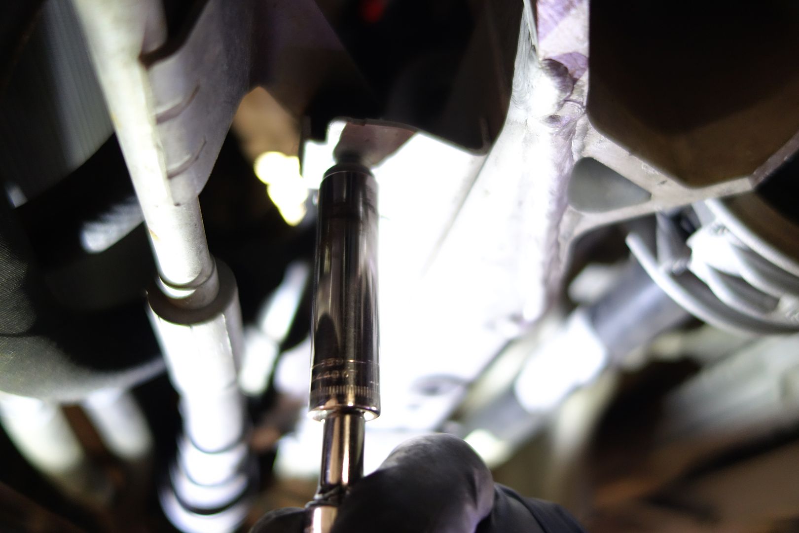
Right by all the pipes you disconnected from the fan you have another ‘U’ pipe which is bolted onto the subframe. It has 3 bolts and one nut. One of the 3 bolts is shorter, that one goes on the passenger side of the rack
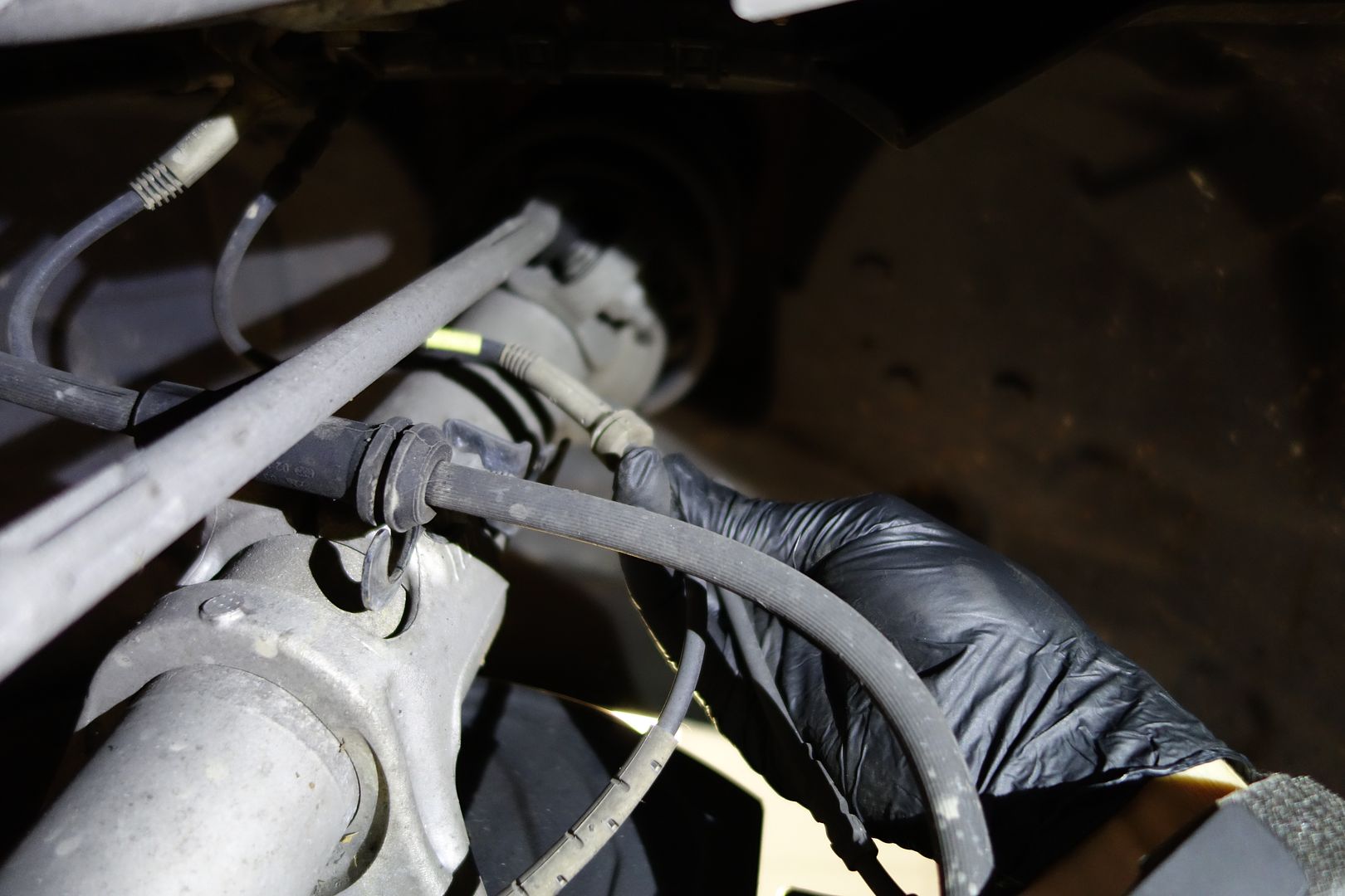
In the wheel well, remove the ABS/Brake lines from where they’re connected to the strut
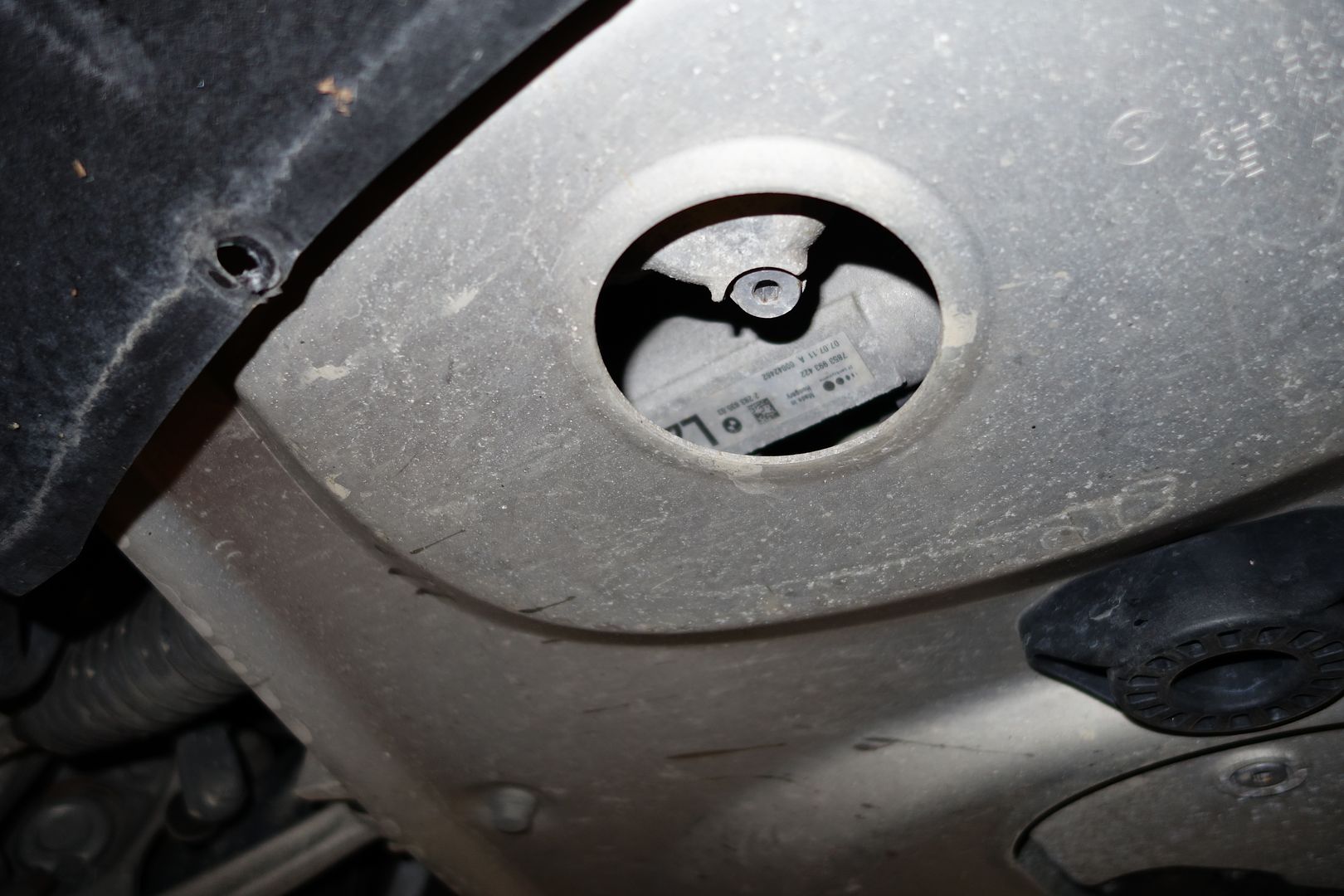
Drain the oil. Remember there are two drain holes in the S65
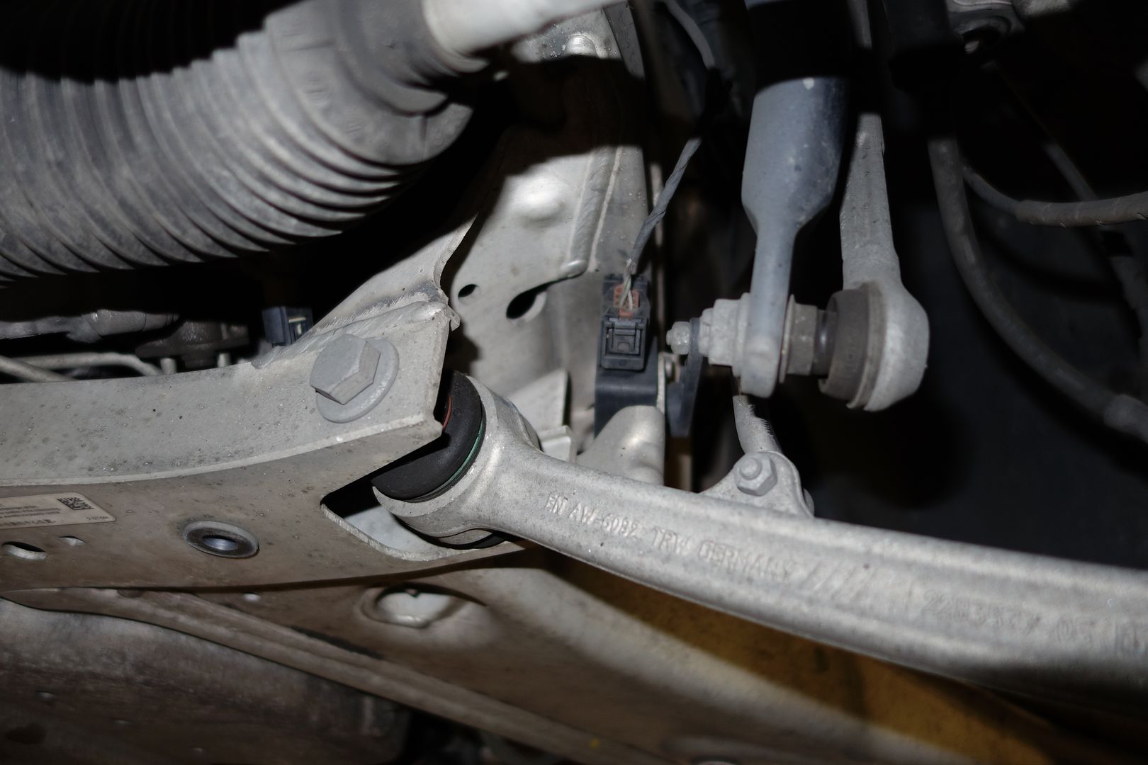
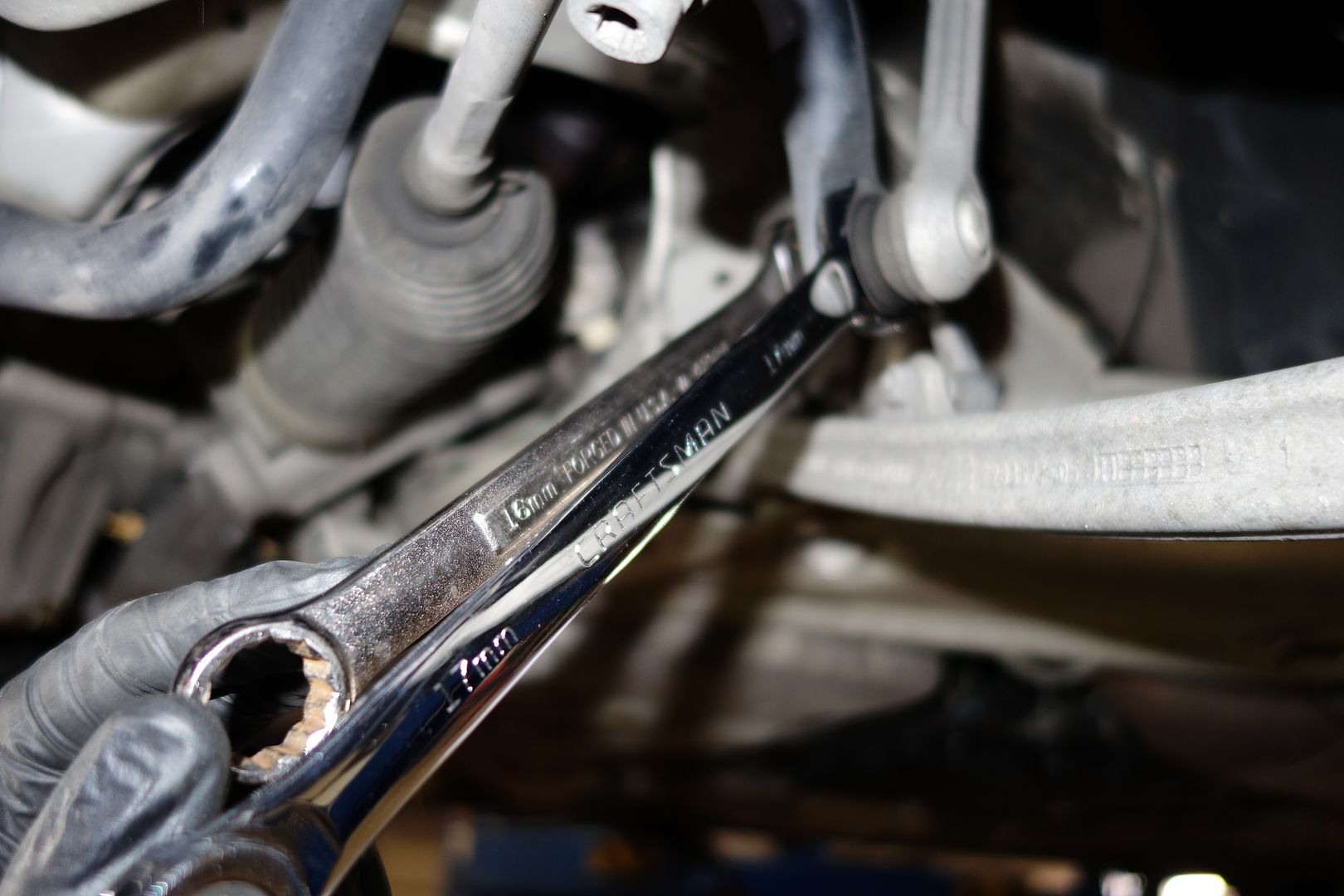
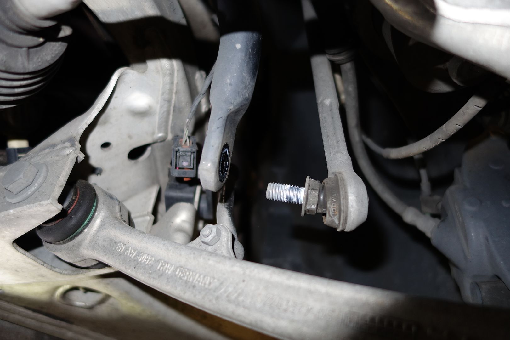
Remove the front sway bar links. I see BMW learned from the bad design of the E46M and now you can use two regular open ended wrenches
The next thing in the way of lowering the oil pan is the belt tensioner. It is half attached to the engine and the oil pan, so we need to loosen it.
As it’s the tensioner it’s very hard to move and we must remove the belt first
Start by taking off the cap to access the bolt underneath. This is what we’ll use to release tension and remove the belt
EDIT: you can remove the belt tensioner once the subframe is out of the way. It's easier.
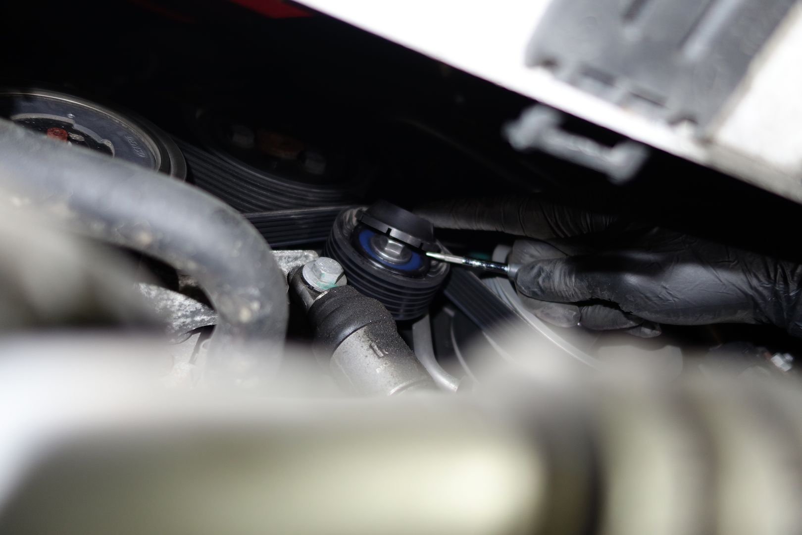
You then use a wrench to release the tension on the belt and slide the belt off. Once the belt is off, release the tension slowly until the tensioner reaches the end of its travel
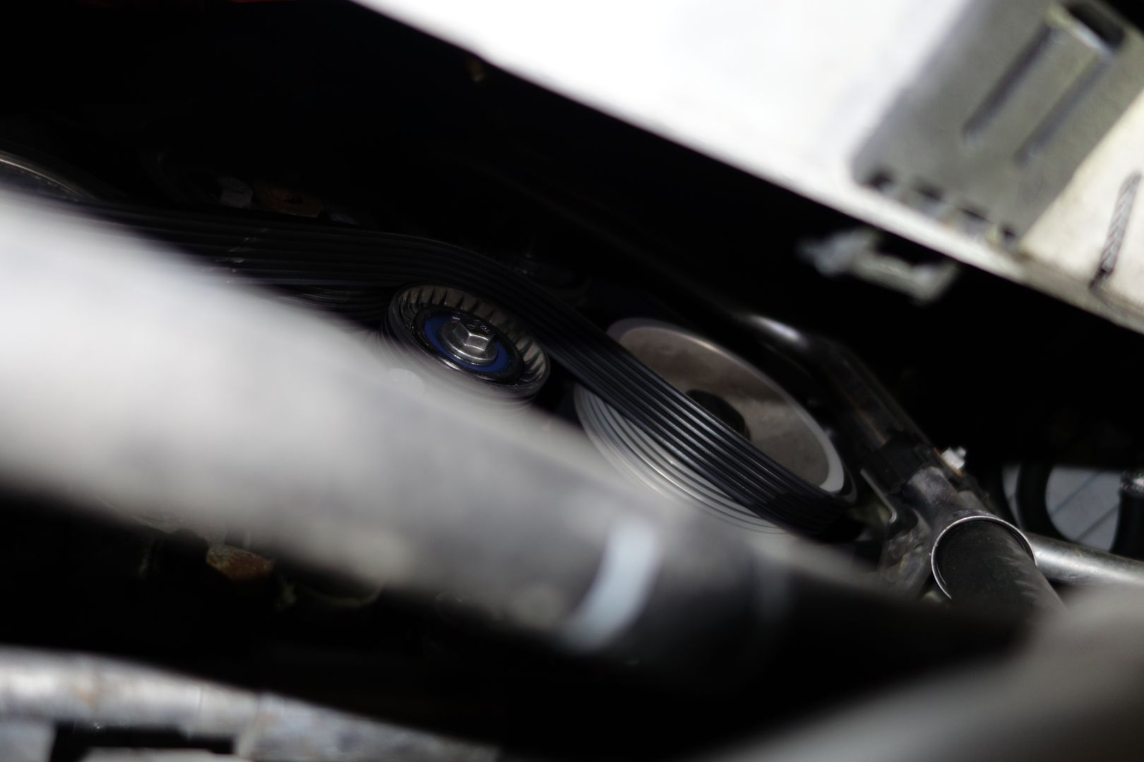
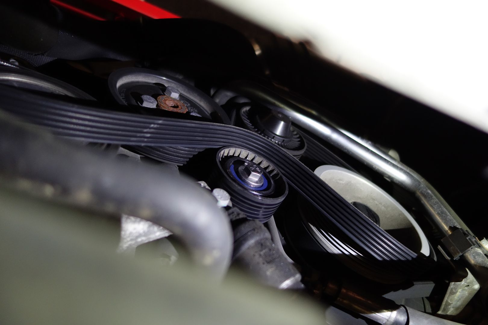
Here you see the base of the tensioner which is still out of our reach because the subframe prevents us from reaching the bolts. Once we lower the subframe a bit we’ll return
Prepare to start undoing lowering the subframe.
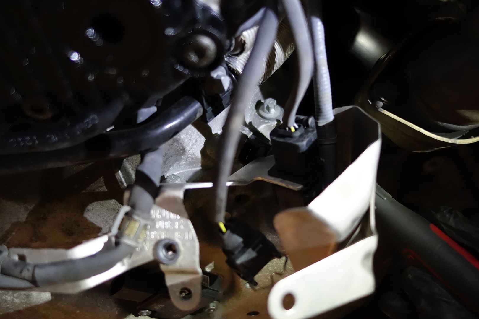
First we unclip different wires. Here you can see two different cables that must be disconnected. One is to the lower left and goes to the arm which controls the xenon position, the other is a white connector

Remove the ground from the engine block
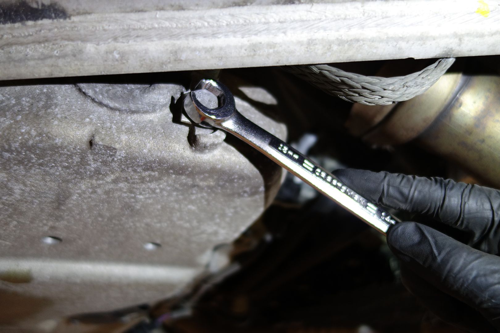
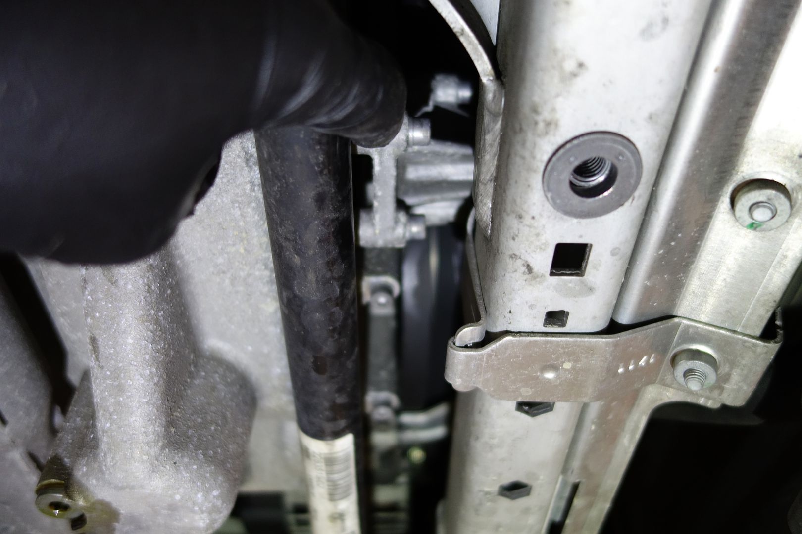
There is a bracket on the front driver’s side of the car. It’s held on with two bolts. Remove them

Notice the wrench I’m holding
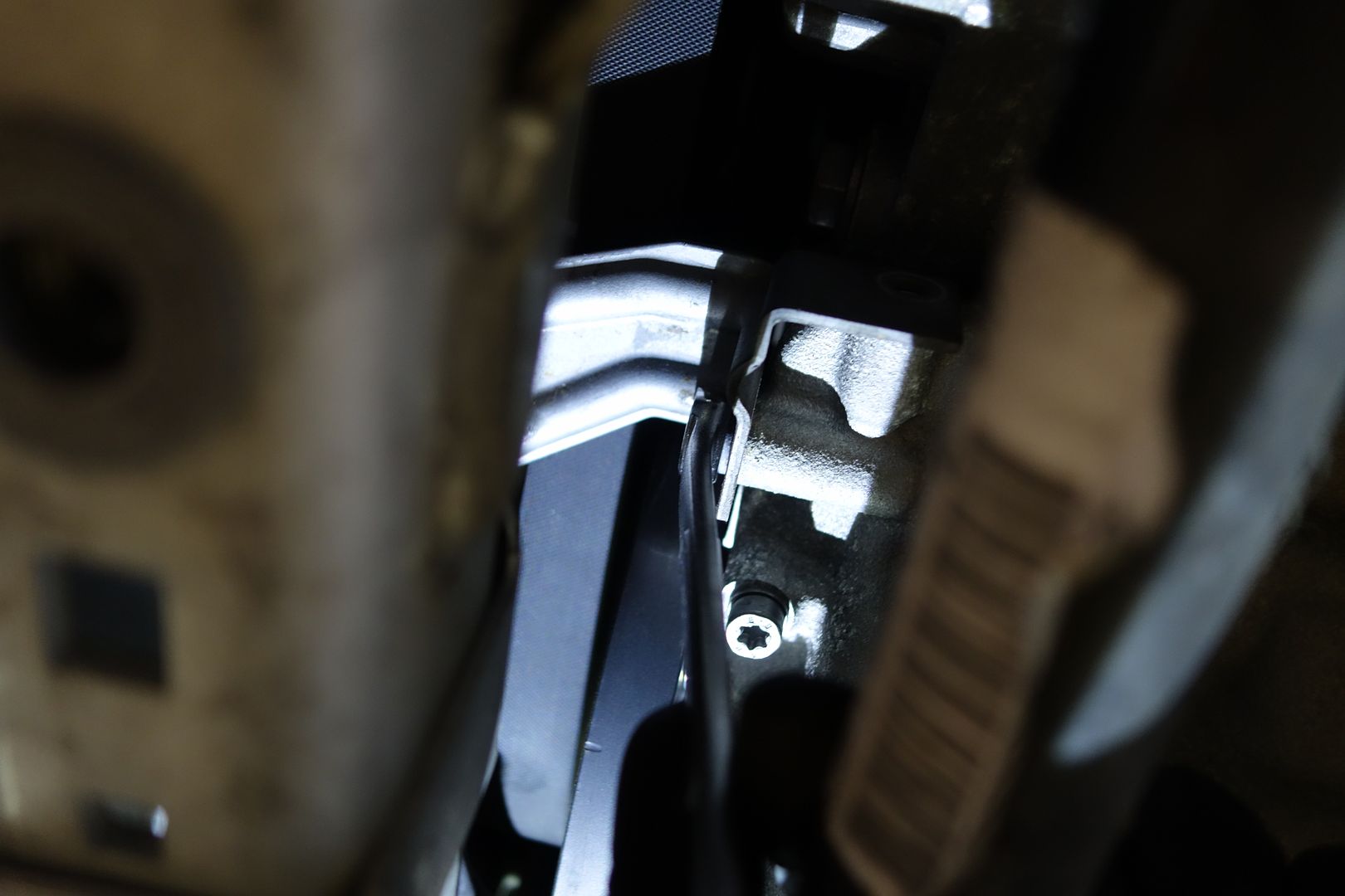
Rotate the steering rack towards the passenger. Do it slowly and you’ll be able to peek at the steering rack bolt that has to be removed. You see this looking from the driver’s side of the wheel well

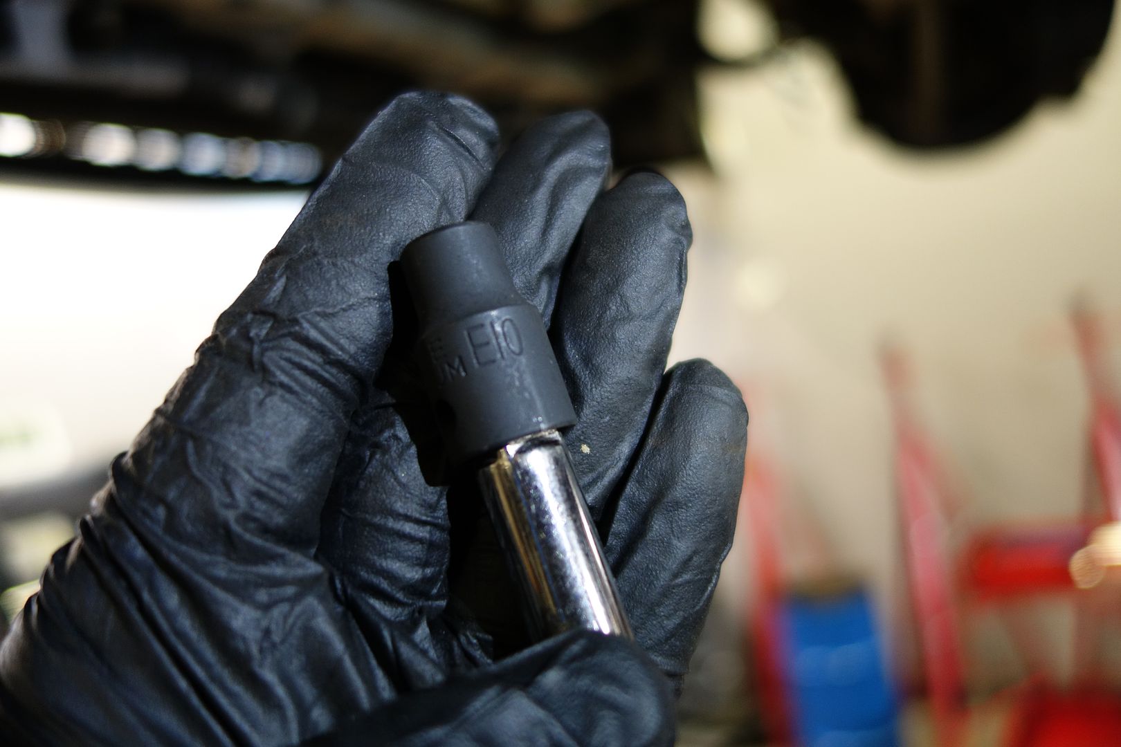
You need a E10 for the steering rack. Before touching this, draw a couple of lines between both parts you will uncouple. This allows you to mate it up exactly as it was. This is not poke-yoke, so it’s possible to set it back up with a crooked steering wheel. If that were to happen to me, I’d just get the car aligned, it is not the end of the world. I drew two lines and was able to reattach it perfectly
Here you can see the two lines
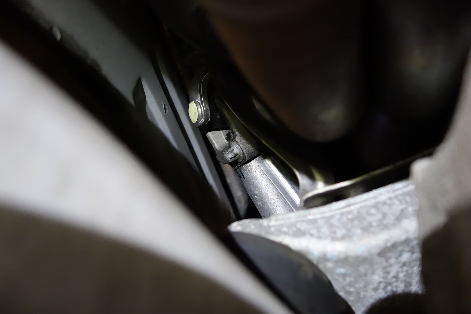
You need an extension to get there
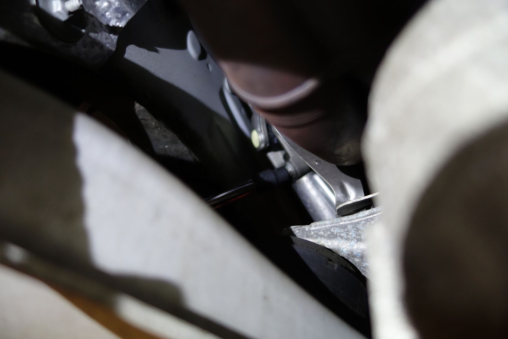
It’s out!
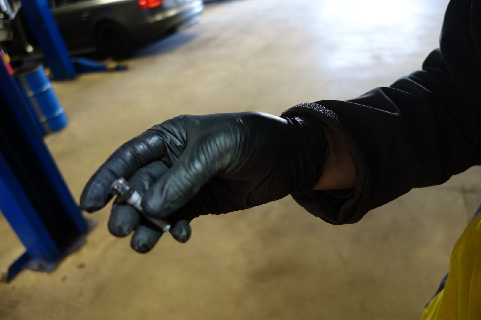
Now we are ready to loosen then lower the subframe. Lets get the 6 bolts first. Note at this point I unscrew the 6 bolts but without removing them. You could also just remove them, the subframe weighs nothing and will happily hang from the suspension
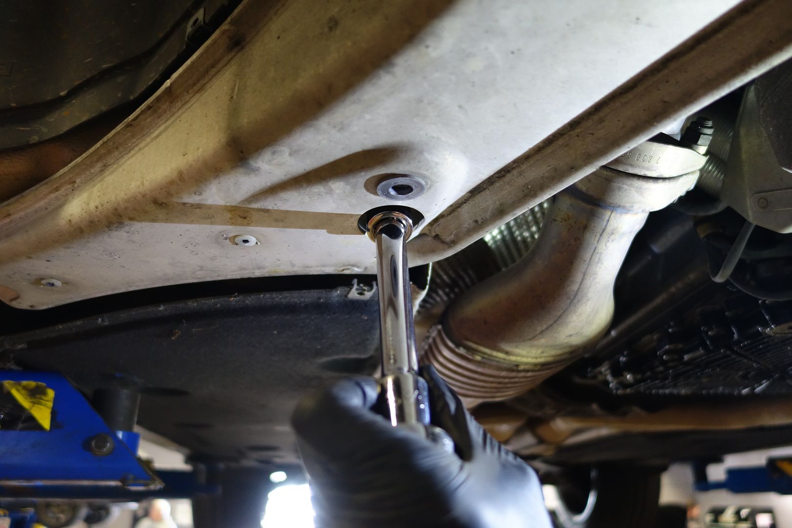
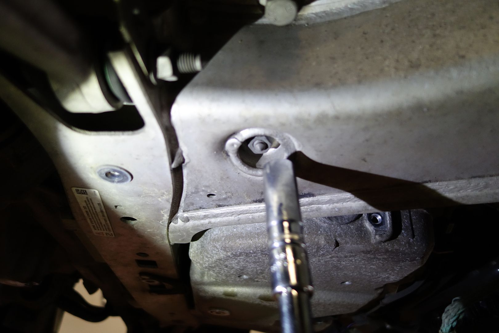
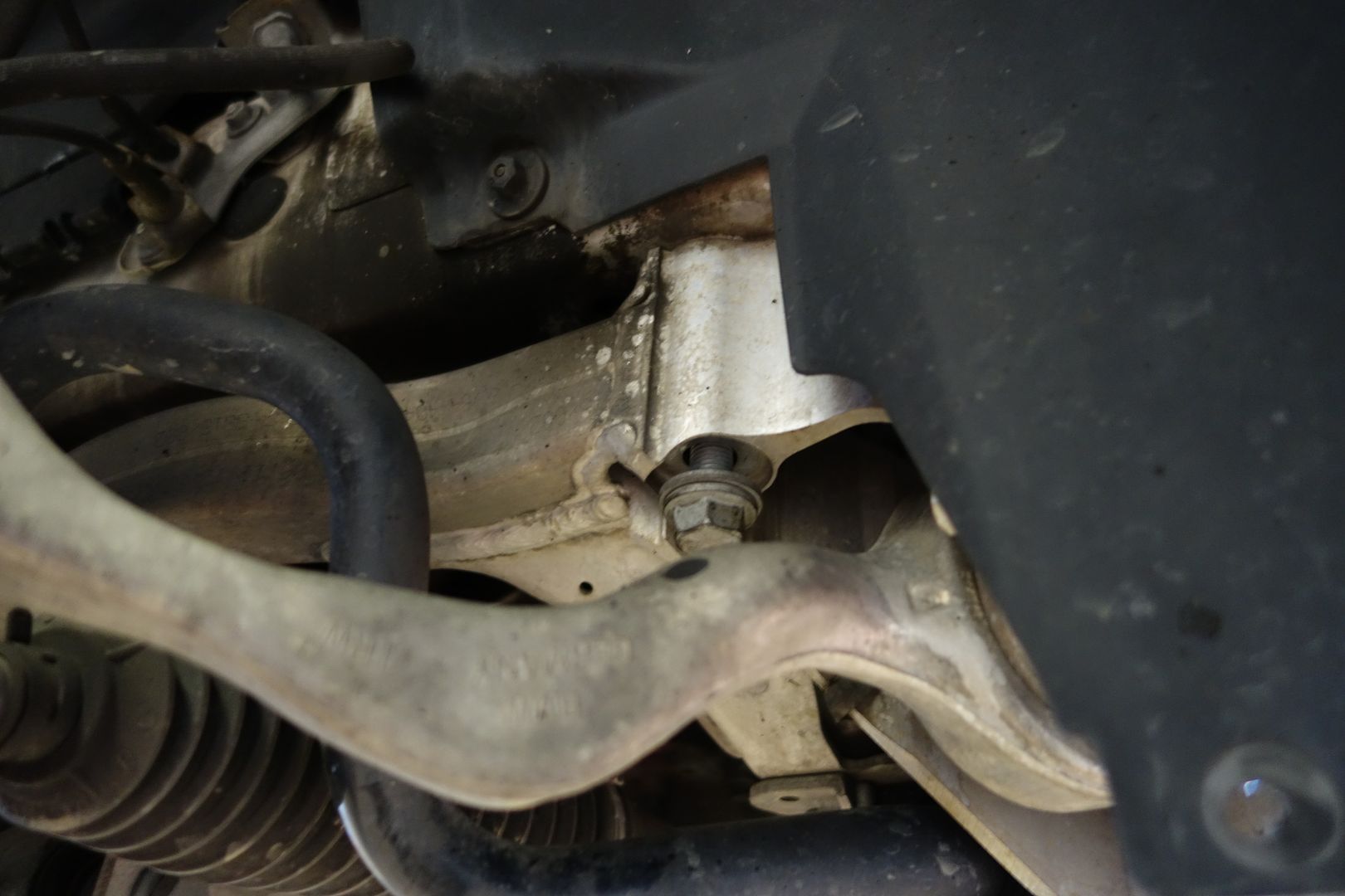
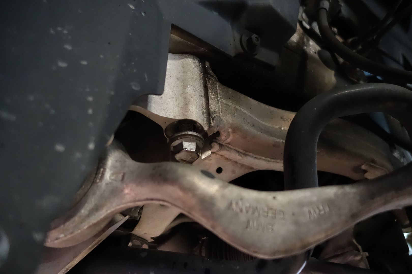

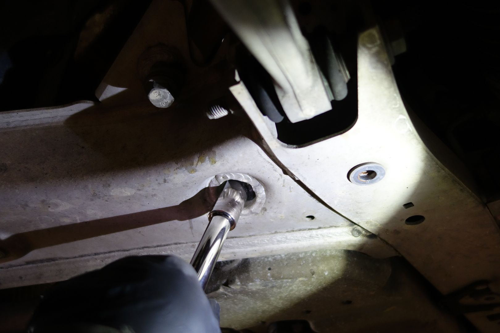

After making sure no cable is about to snap, I release the bolts completely
We can revisit the tensioner now that the subframe is a bit lower. Remove the three bolts
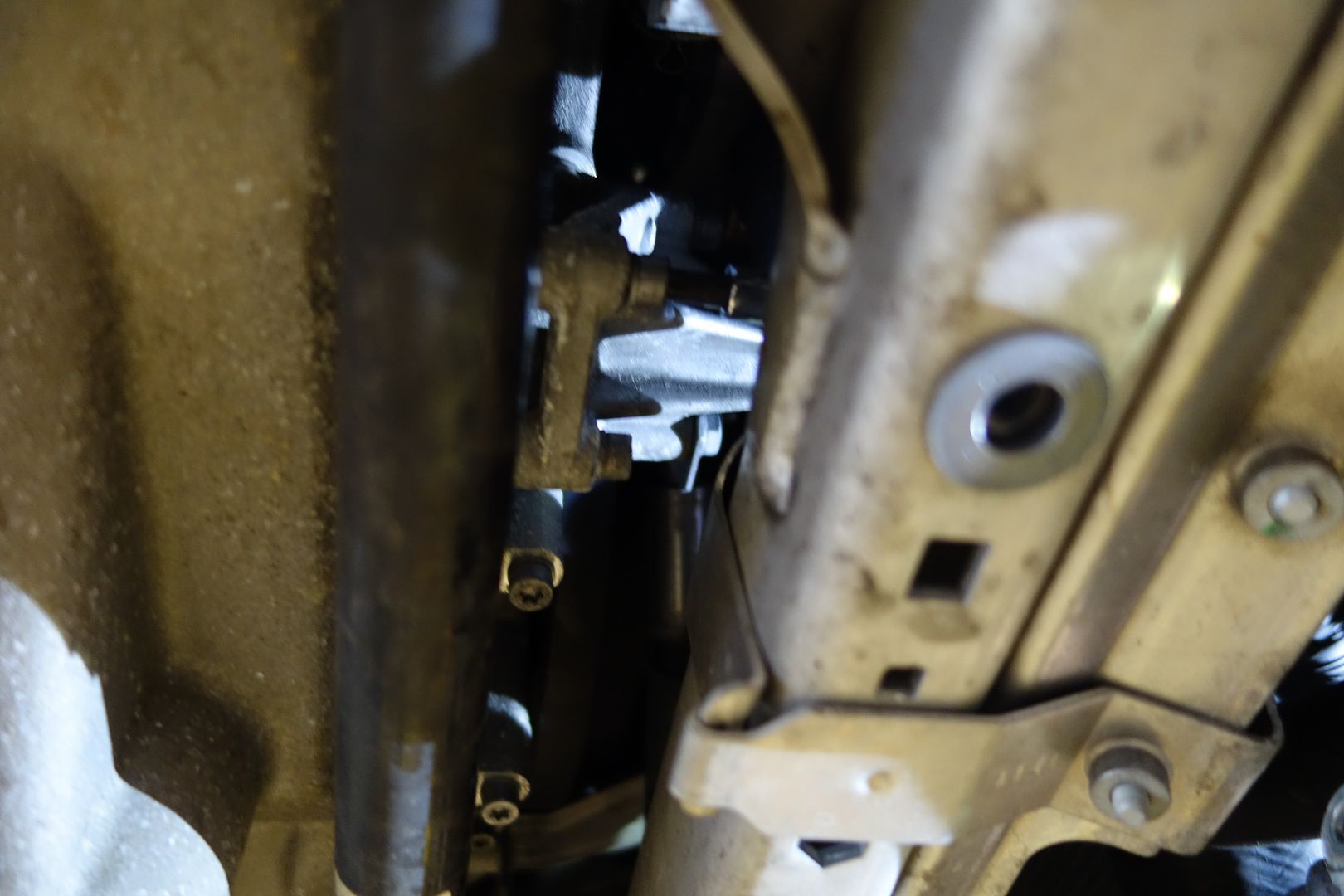
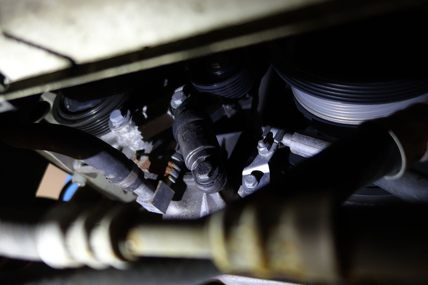
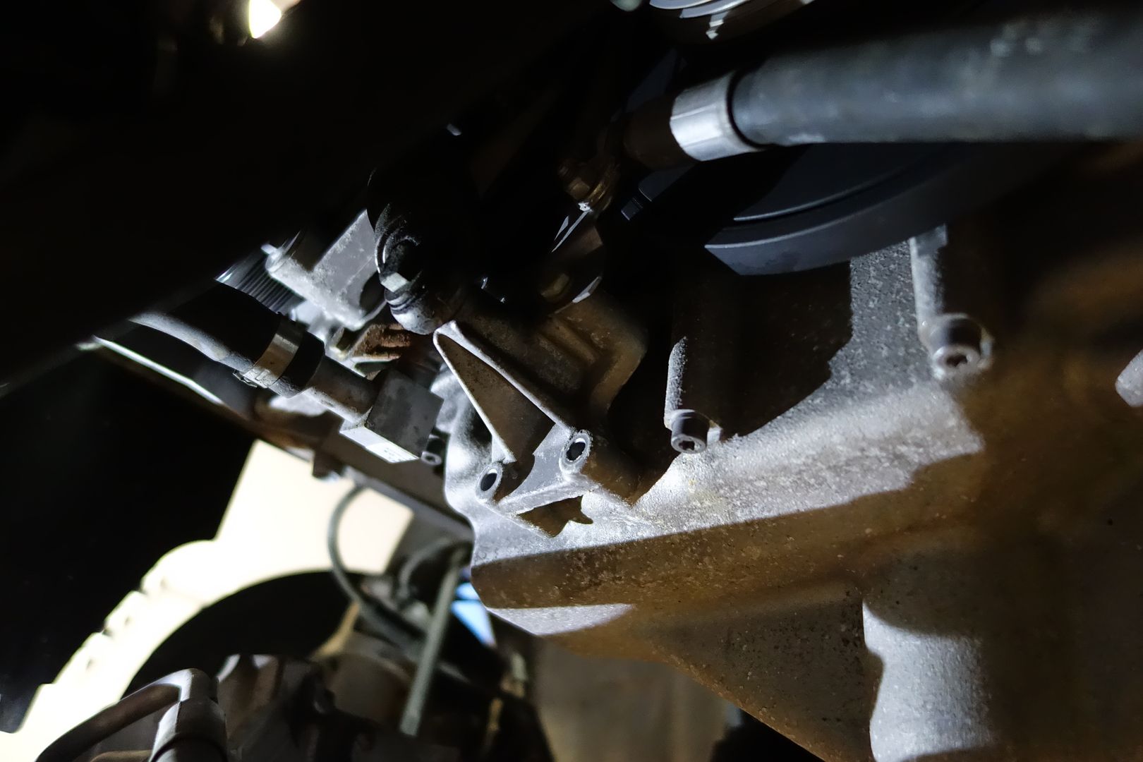
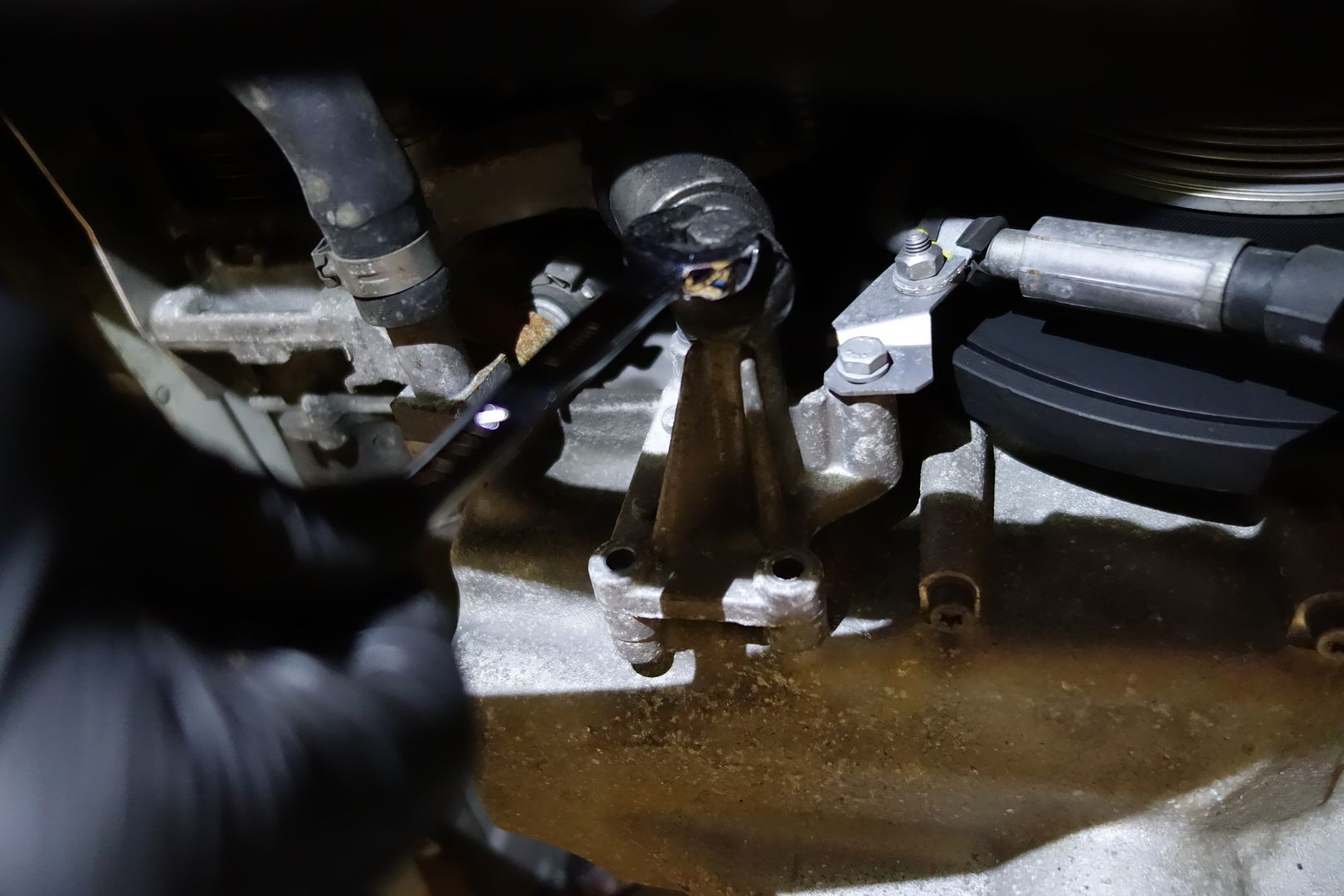
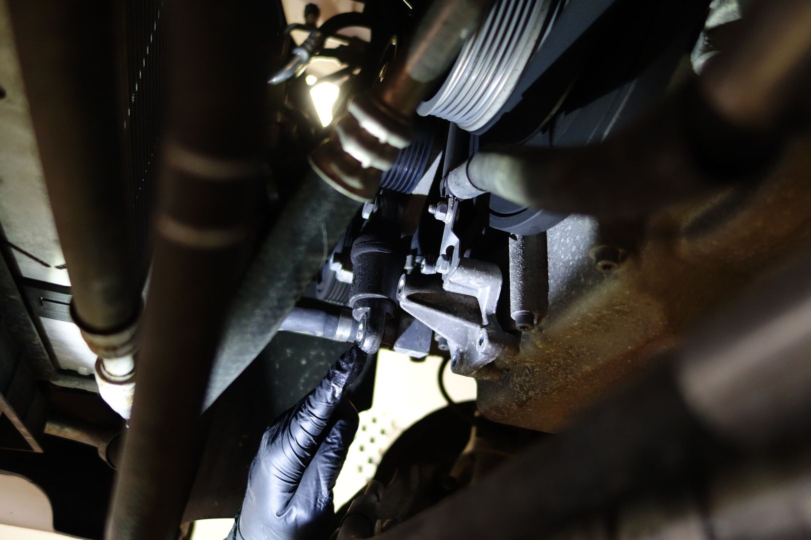

Go to the back of the oil pan where there’s a surprising amount of cables. Unclip them and release the harnesses
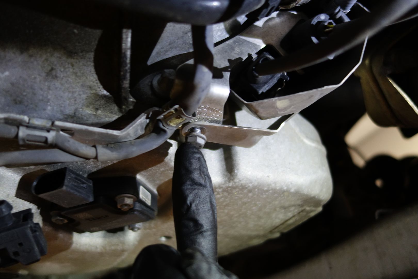
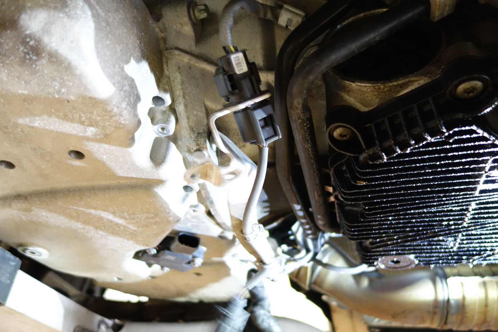
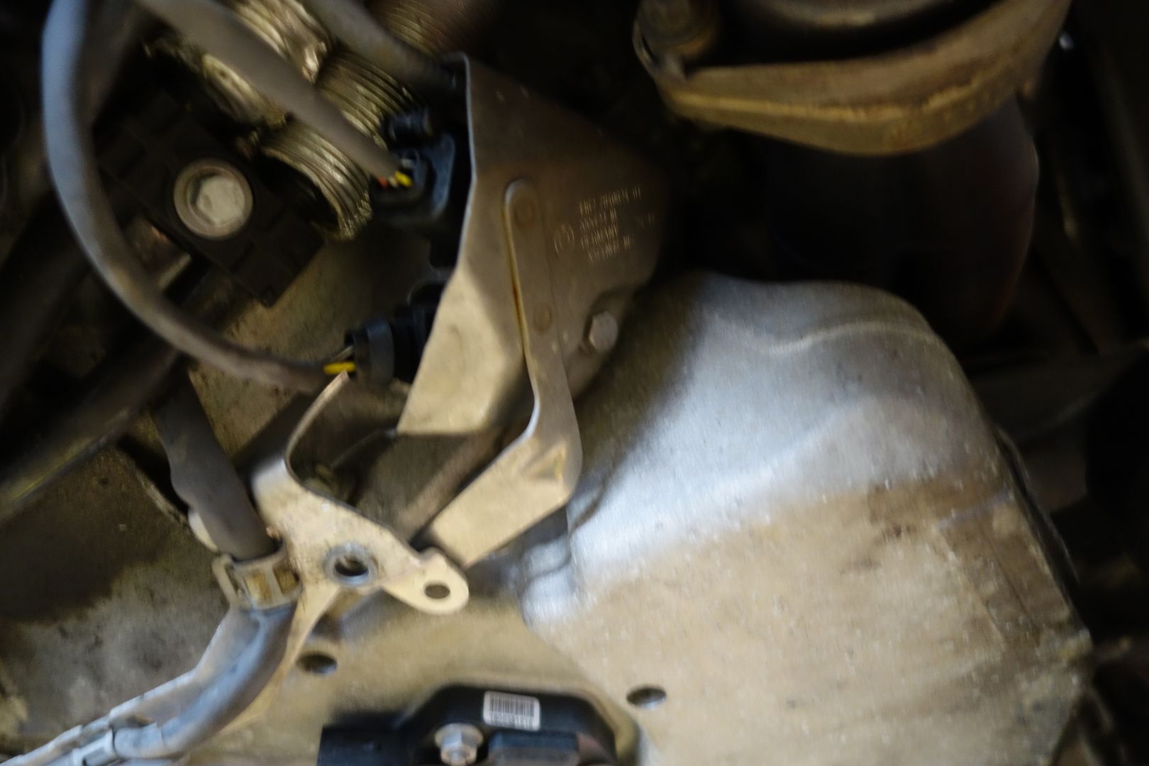

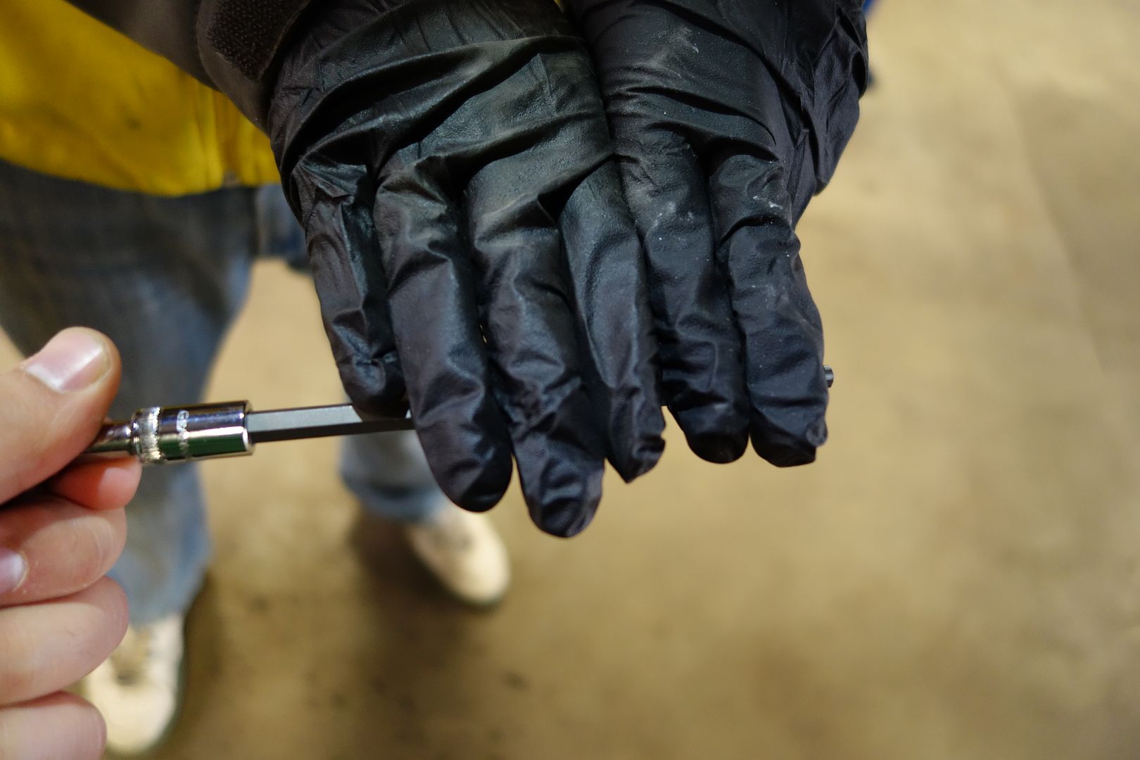
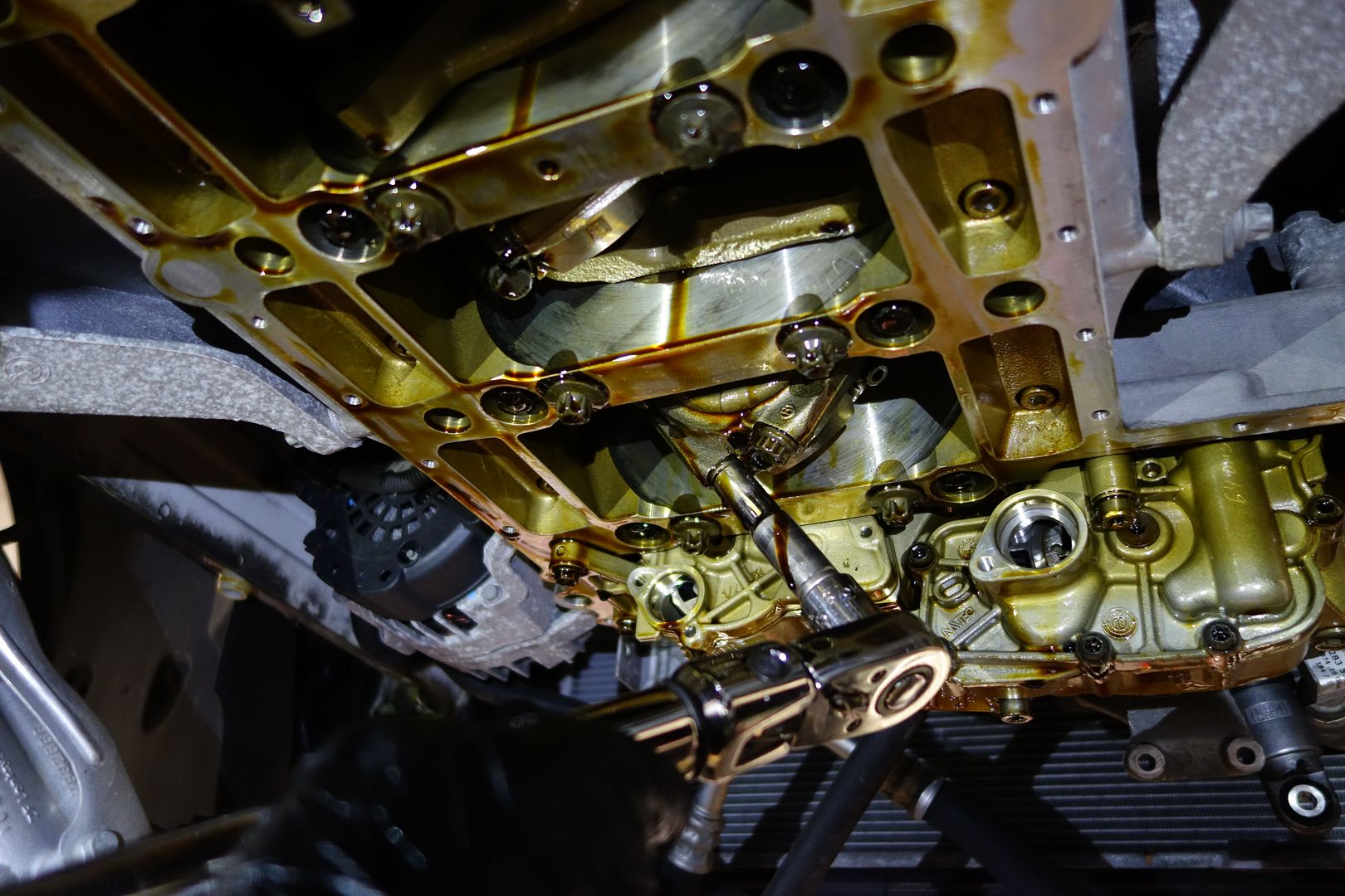
It’s time for the oil pan bolts! Please take note of how long the T30 needed is. I used a 6 inch one because the 4 inch 'extra long' one I had bought for this job was insufficient
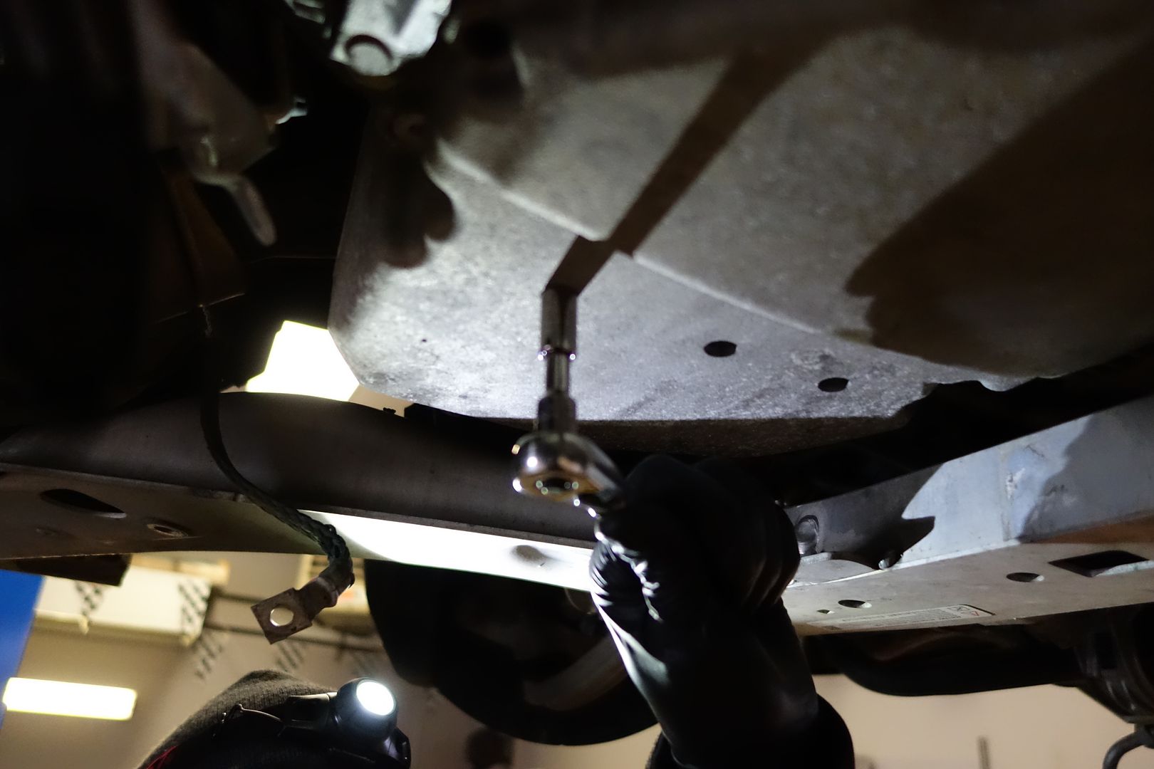
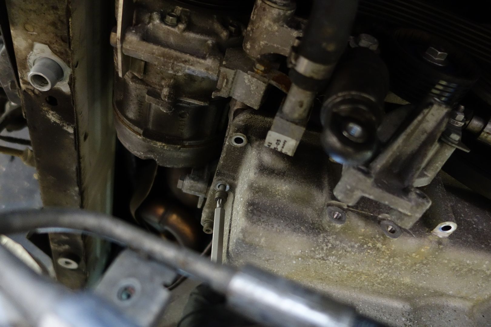
Remove all the oil pan bolts. There are many of them. The ones you need the extra long T30 are in the back of the oil pan
I followed smart people’s advice and inserted the oil pan bolts into the cardboard part that comes with the new oil pan gasket. There are a few diagrams I made. Left is the front of the engine, right is the rear. I put the car behind some pictures to make it extra clear. Note the two different lengths of bolts that are used, so take note!

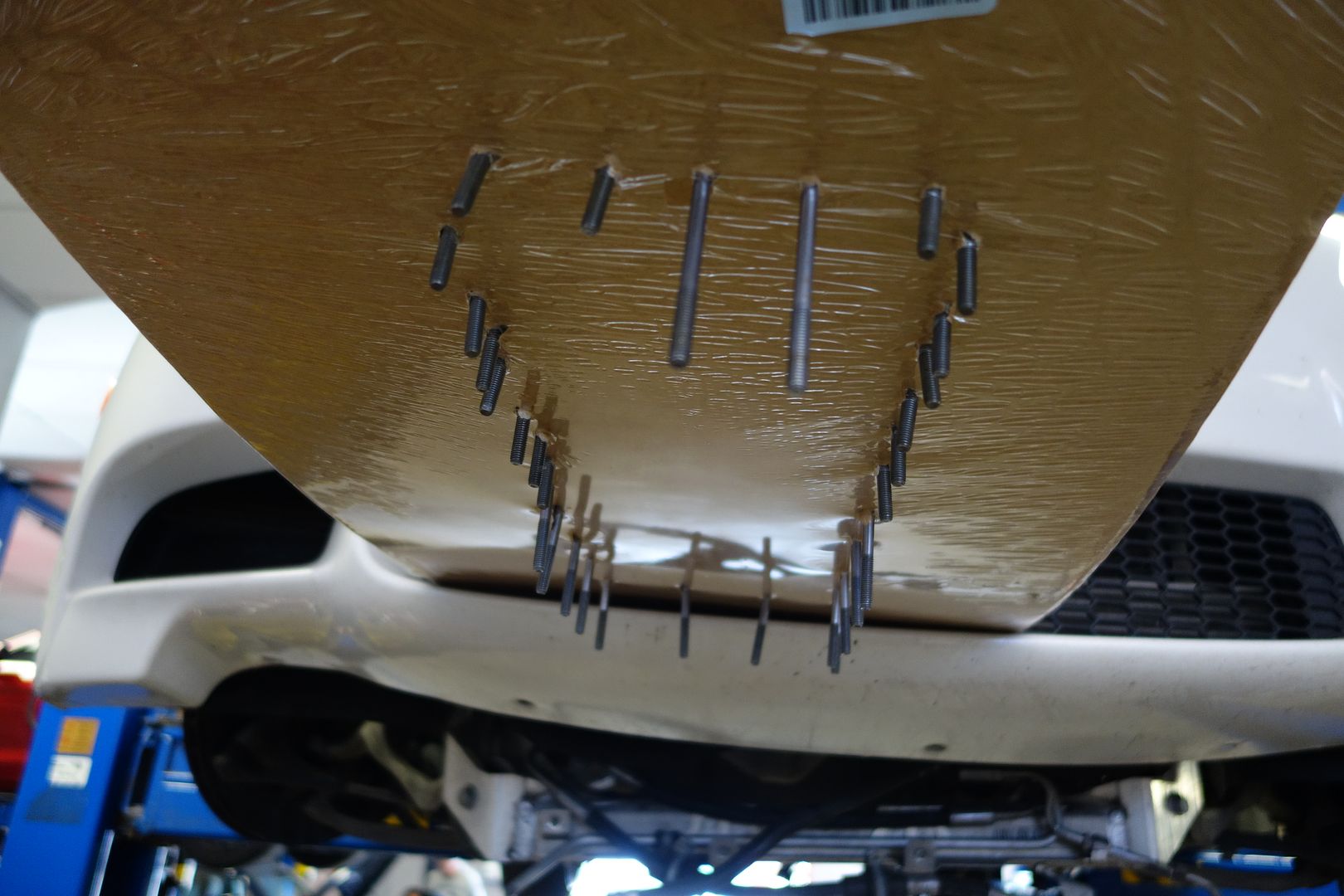

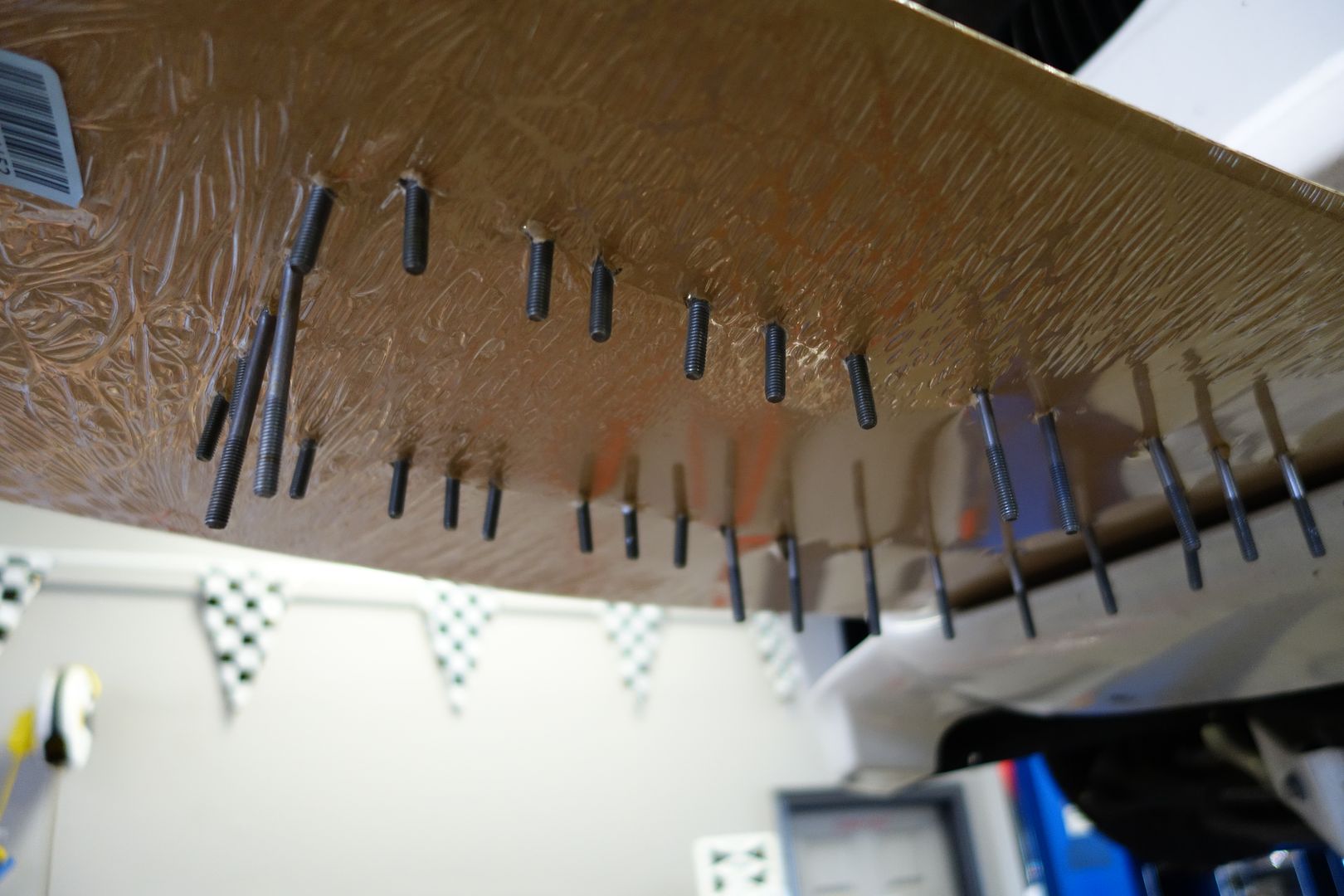
Just like in the E46M, the back of the oil pan/tranny interface has 4 long bolts that go into the oil pan. I used an open ended wrench on 3 of them as a regular socket doesn’t fit
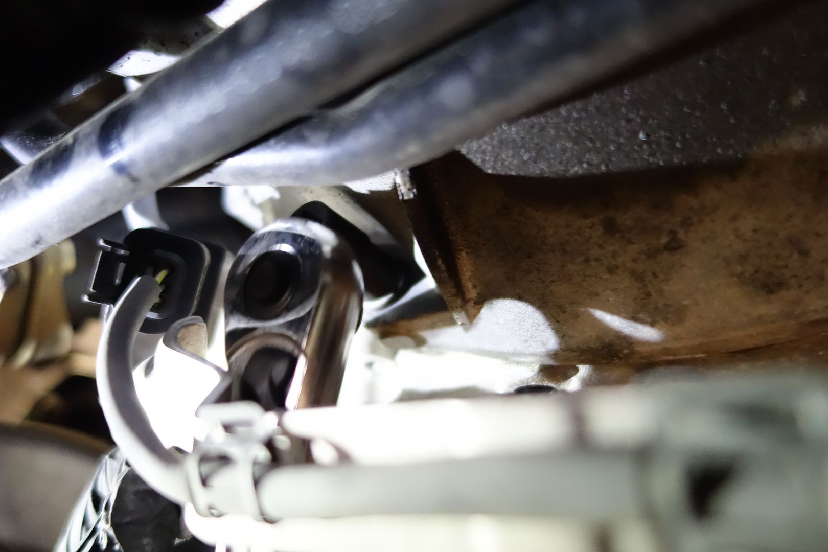
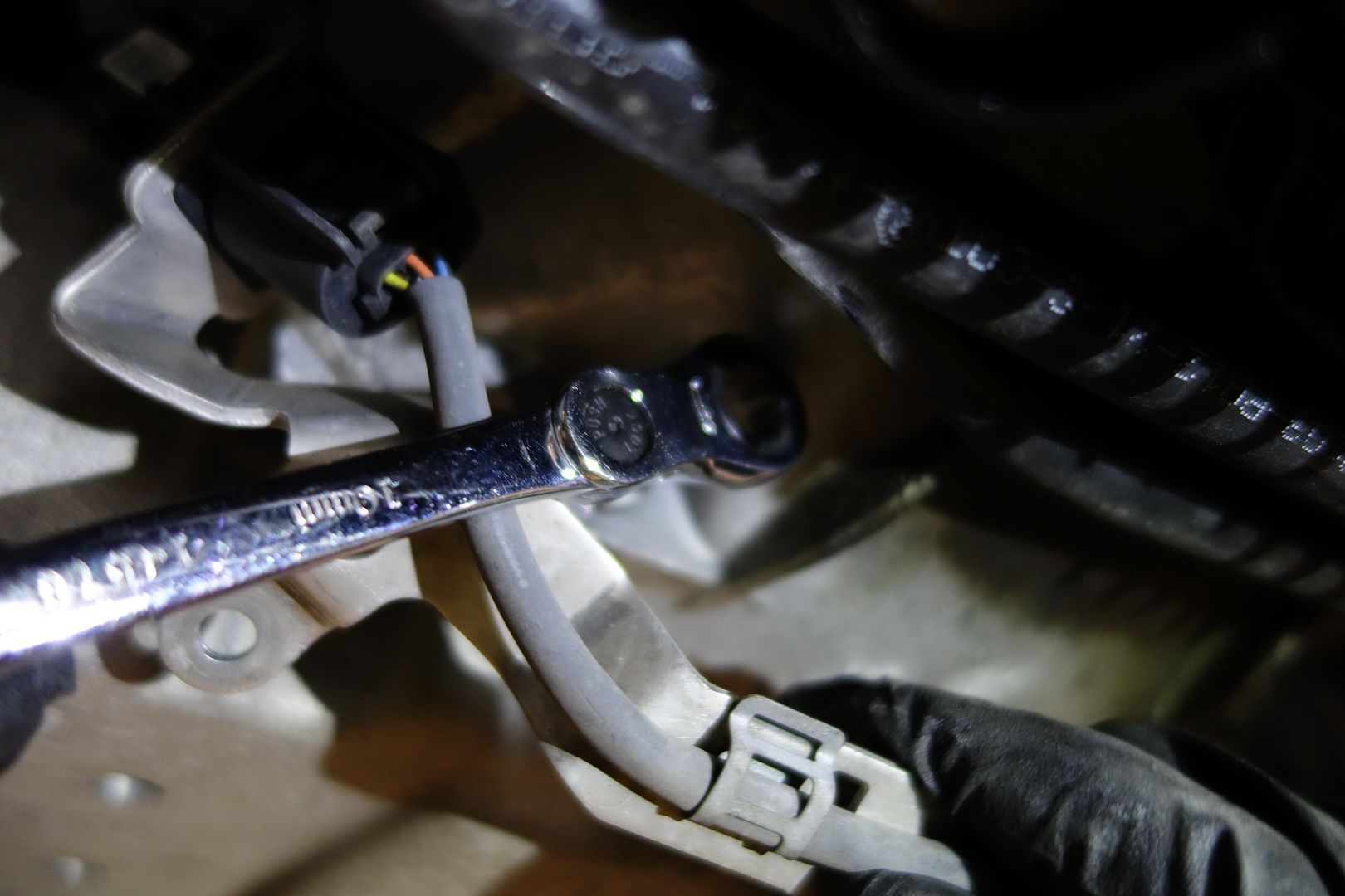
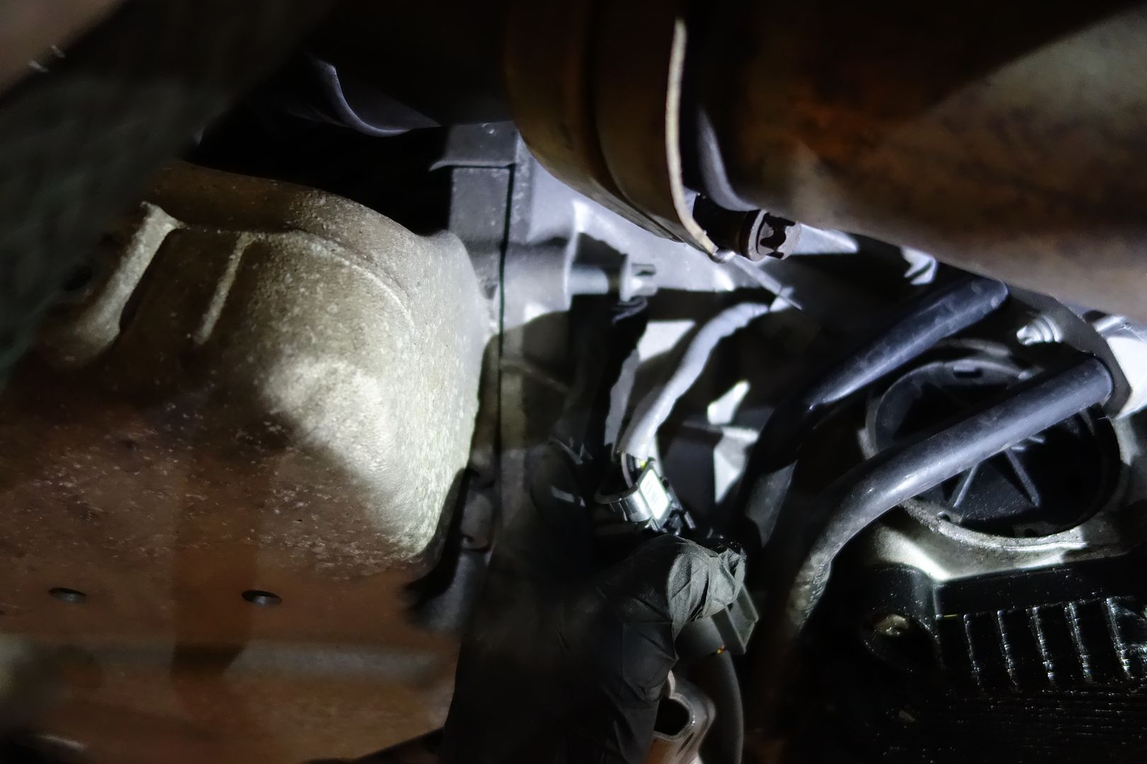
After that, the oil pan just falls down a bit. An oil pipe and the subframe avoids it from going far
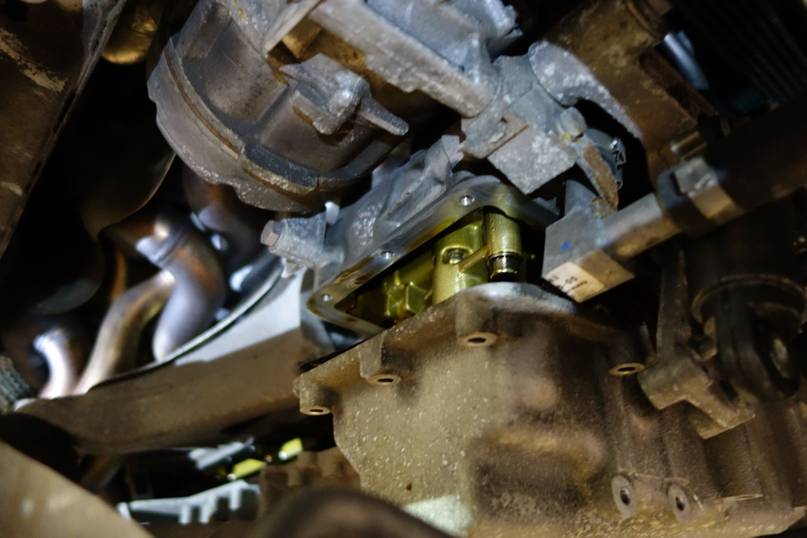
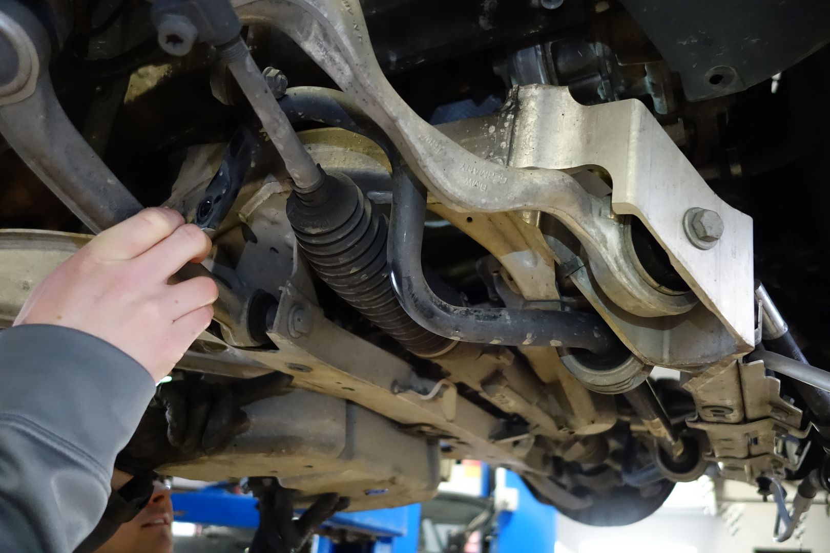
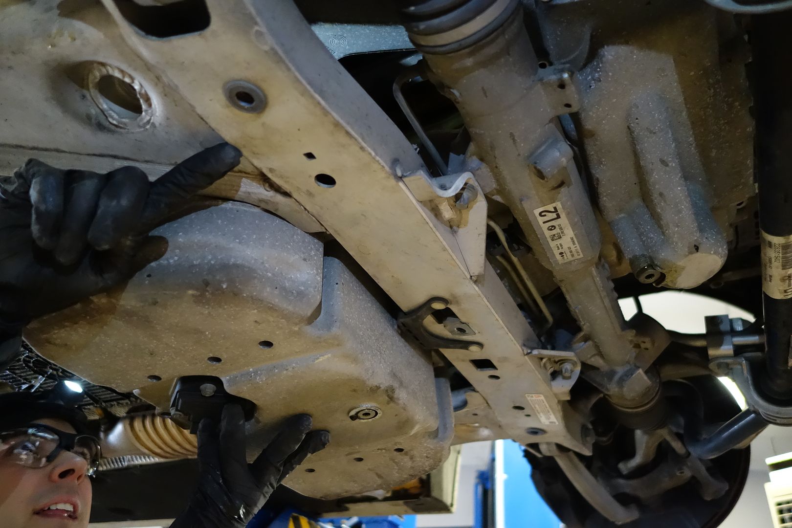

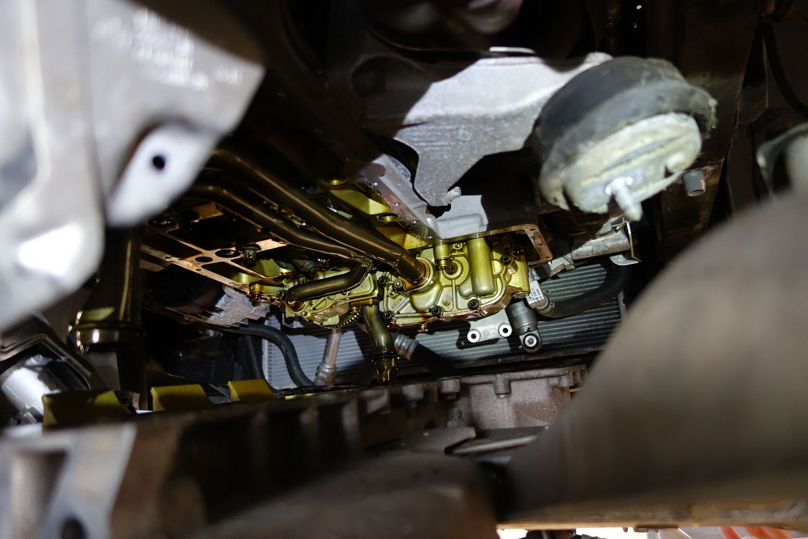
Here you can see the fat pipe in the front which is standing in the way of our progress
UPDATE: it's possible to remove the oil pan without removing this pipe. You just have to finesse the oil pan into the right position.
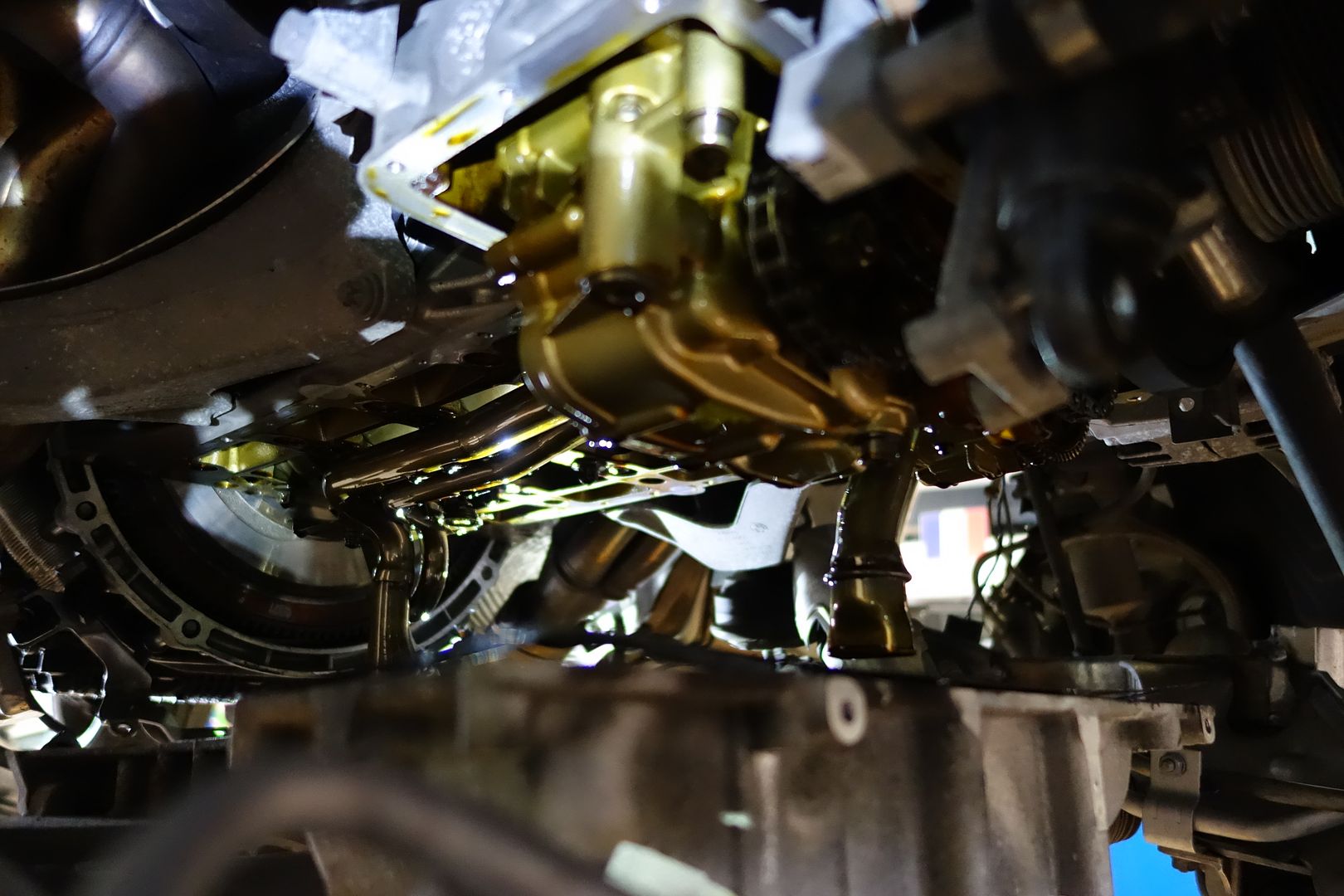
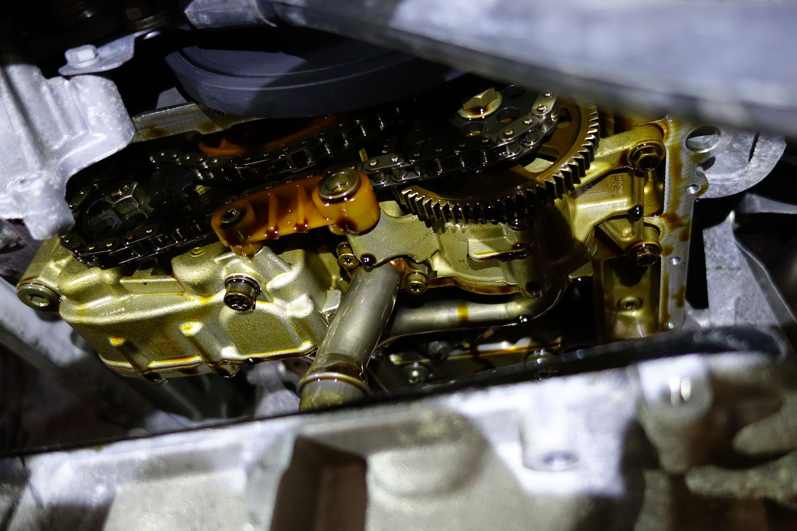
Time to remove that pipe. It’s held on with two screws and has a mini gasket. Remove the short fat pipe. Note that this pipe has threadlocker on it, so be sure to reapply blue threadlocker when reassembling


Now you can drop the oil pan further
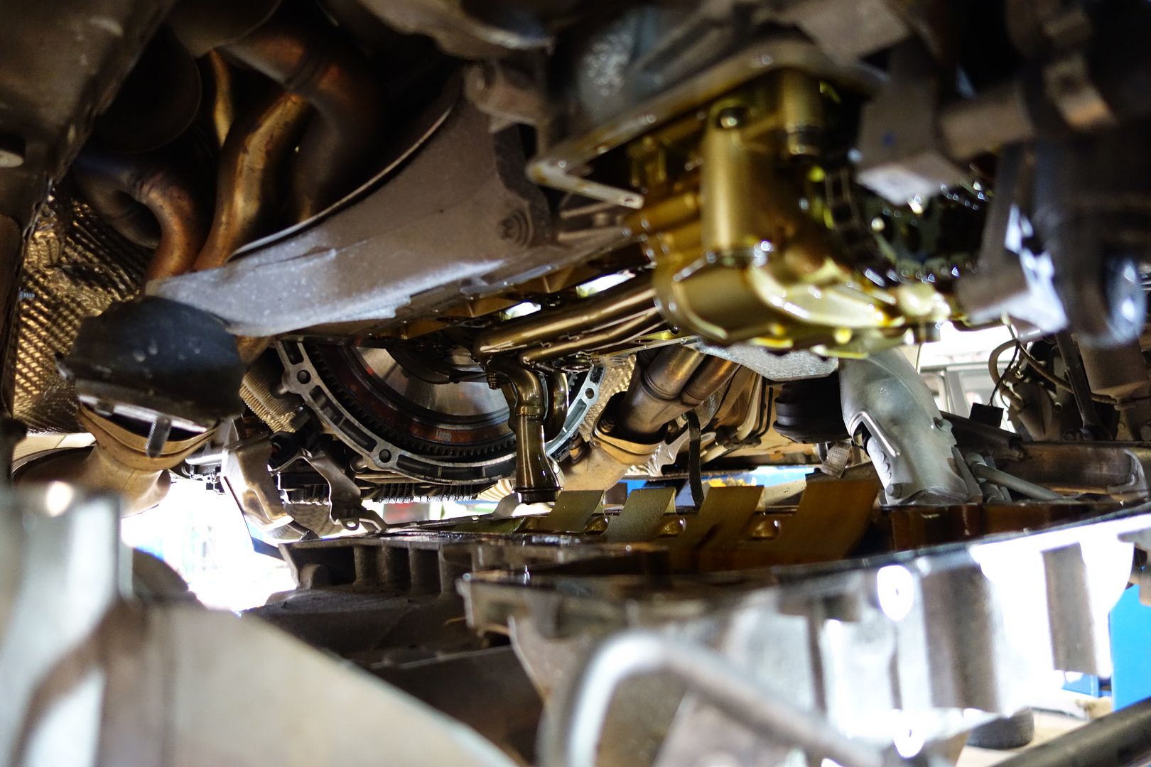
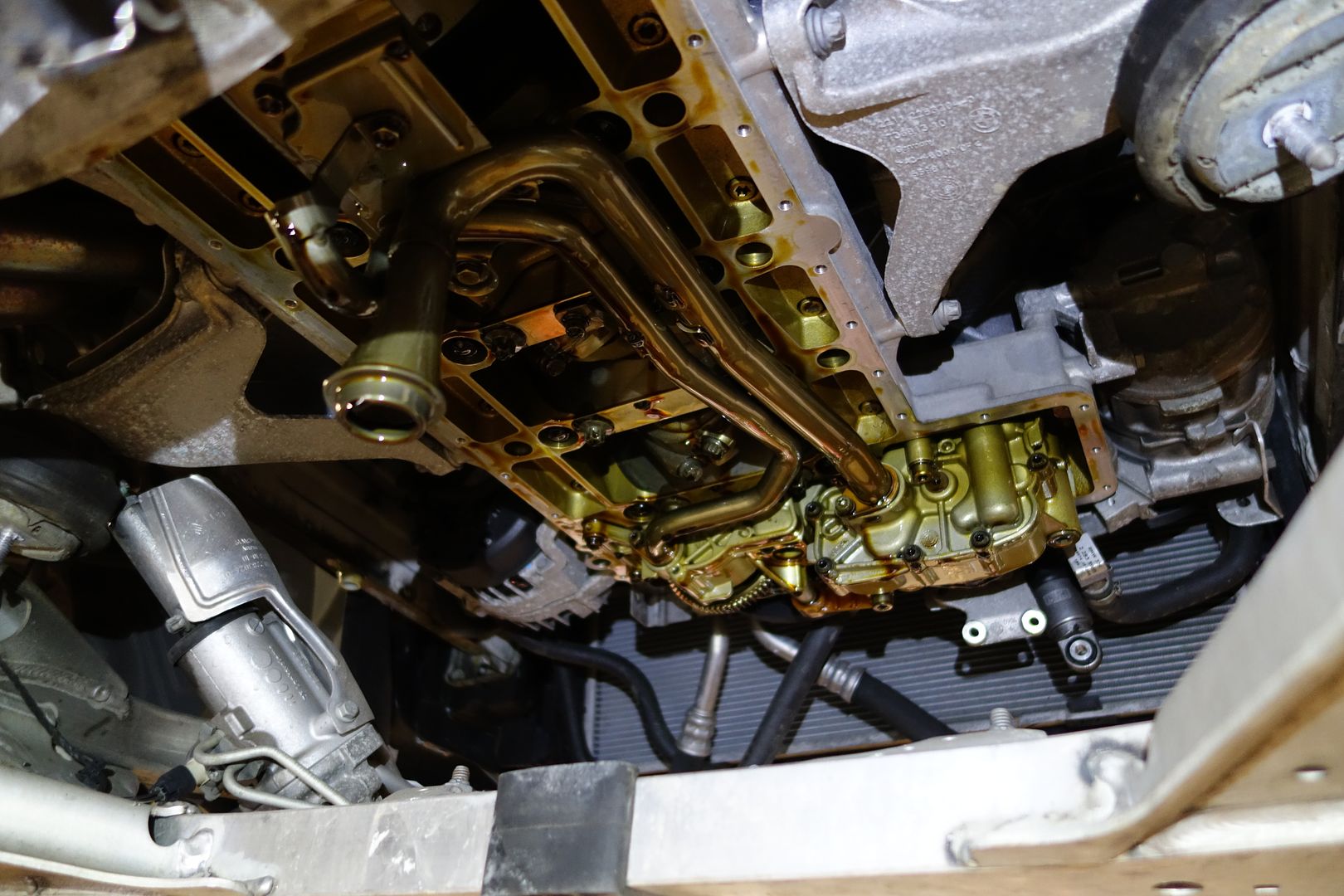
Next up are the two remaining oil pipes plus the supports. Remove them all. Note that all this hardware has threadlocker on it, so be sure to reapply blue threadlocker when reassembling
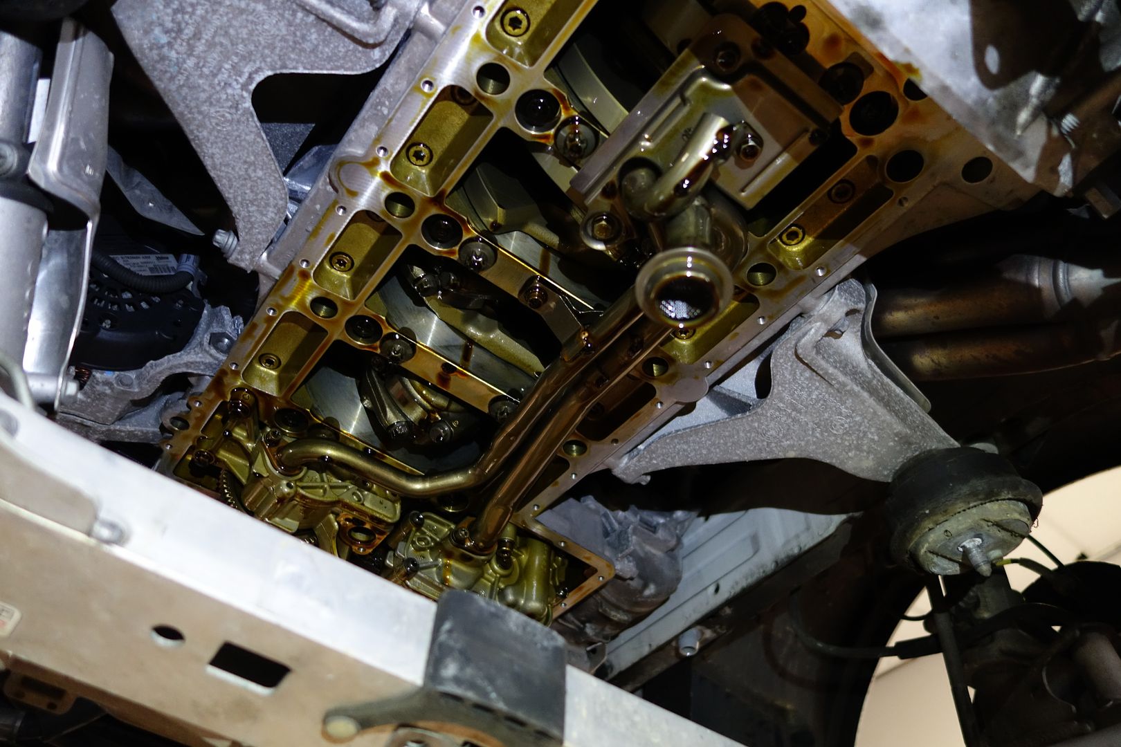
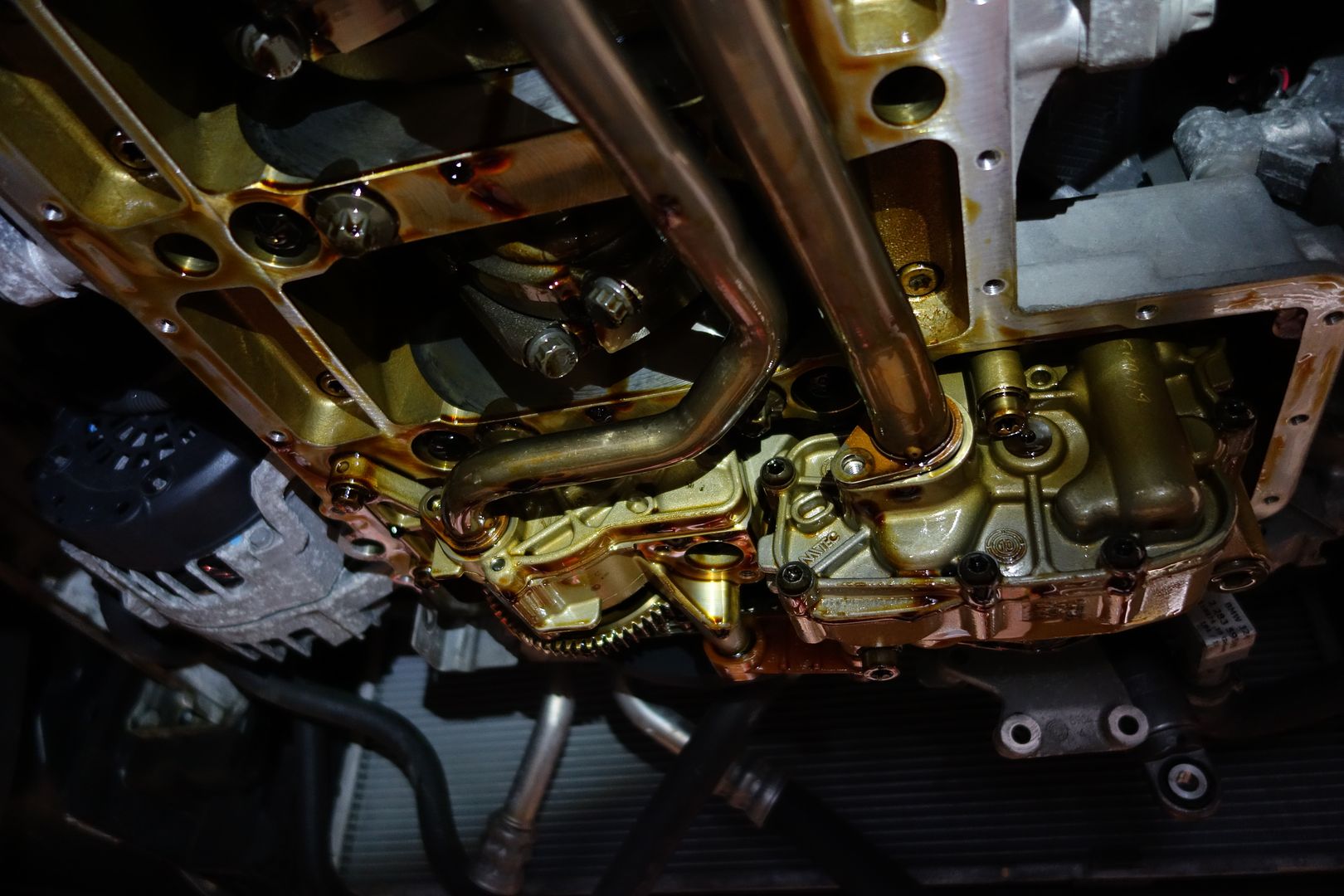

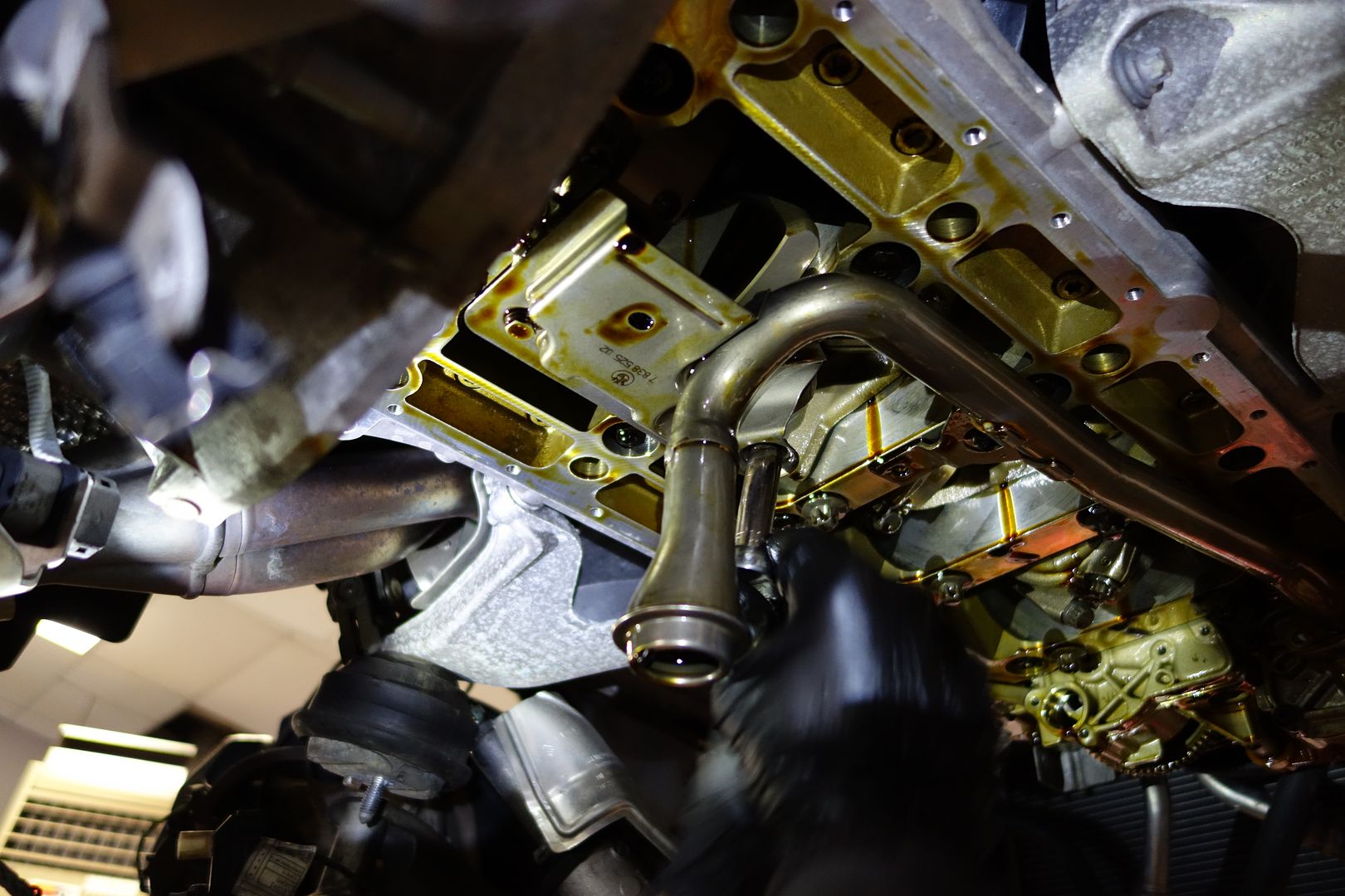

Finally, we can start accessing the rod bearings!
Cylinder 1 (most to the front of the car) is in the perfect position. You can do rods 1 and 2 without rotating the engine.
I went cylinder by cylinder completing the work
After loosening the two bolts that hold a cap, sometimes you need to give it a little nudge with a rubber mallet
Note these are cracked forged rods which, besides being awesome, are cylinder and side specific. That means cylinder one’s cap only mates to cylinder one and the left side must go with the left side. I guess enough people screwed this up with the E46M3 that they started numbering the sides, so now one side of each rod and cap has numbers are the other doesn’t.
Once you have a cap in your hand, you remove the old bearing. Easiest way I've found to do that is rotating it from the belly sideways, if need be one way and the other, and it'll slide right out.
Next get a new bearing, insert it into the cap (it is a bit springy, but it does fit), note that top and bottom bearings are identical in my case. Some BE Bearing sets will be marked 'top' and 'bottom' shells, so if that is the case be sure to put the 'top' shell into the rod, the bottom into the cap. The ones I received were undesignated tops and bottoms and could be installed interchangeably
Then, get some clean oil or assembly lube and cover the surface of the bearing. I misplaced my assembly lube but apparently oil works just fine according to technical folks, so I used that. I used a clean glove to spread the oil on, replacing it every time it got dirty because I touched another surface
First insert the bearing on the cap (where you can see what you're doing, and practice doing it by feel only), then the rod. To access the upper bearing just push the piston up by the rod and then nudge the old bearing sideways to get it out, just like you did on the cap.
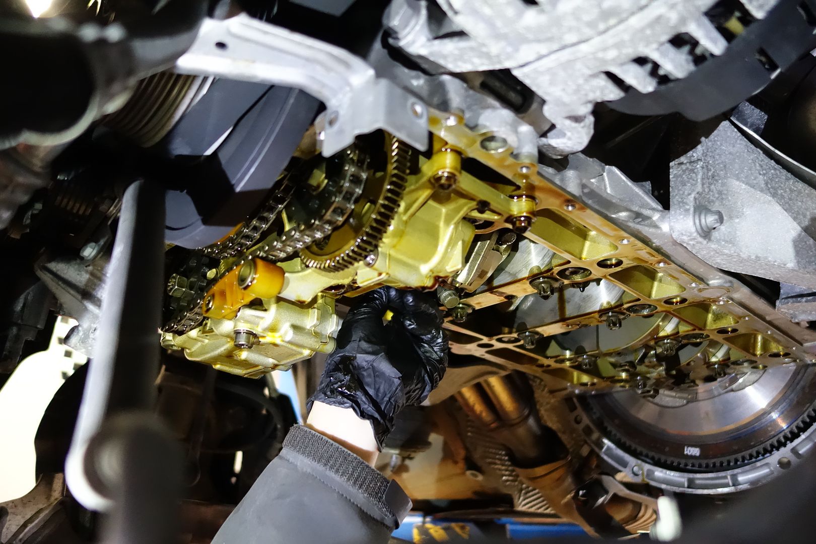
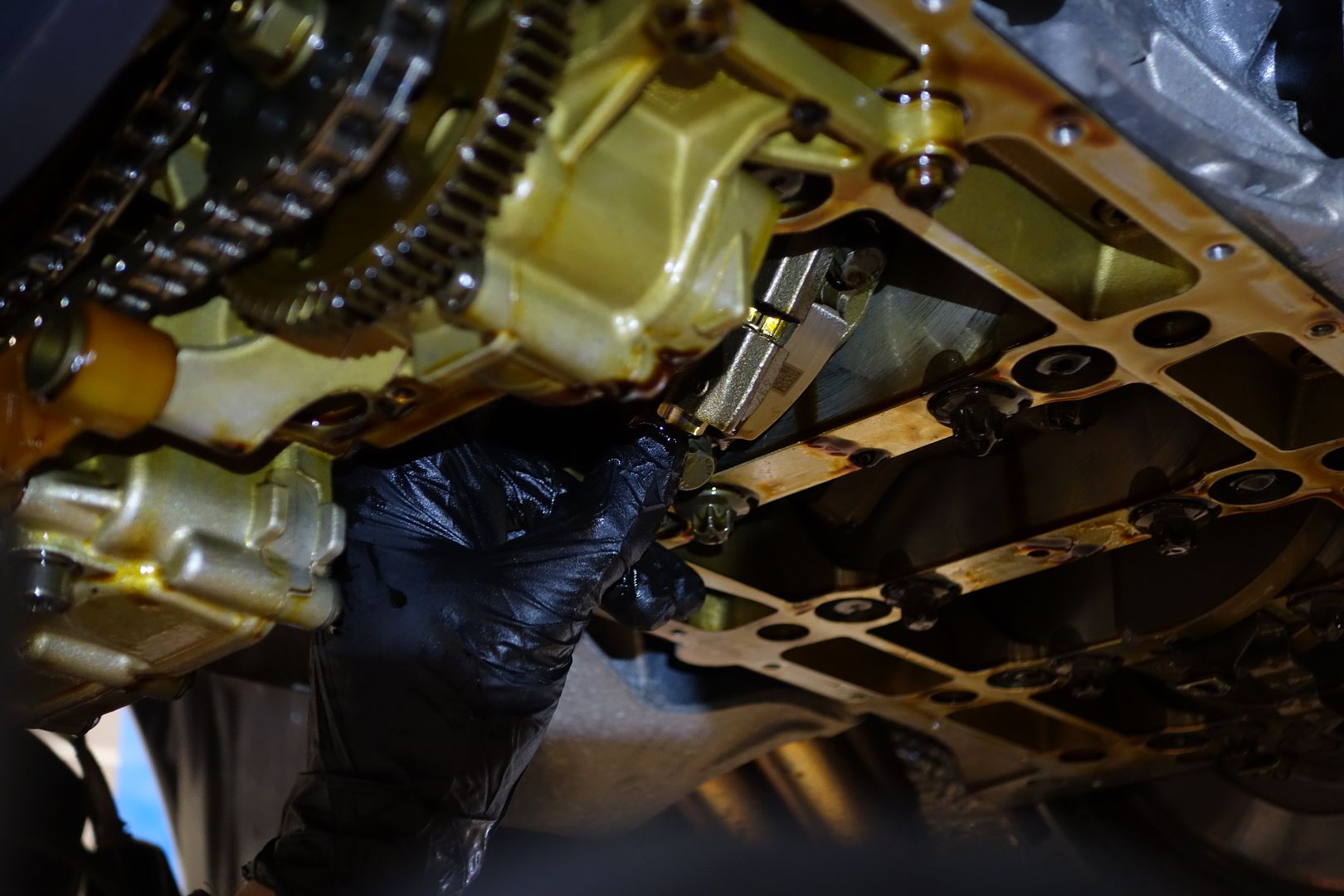
Cap 1 removed!
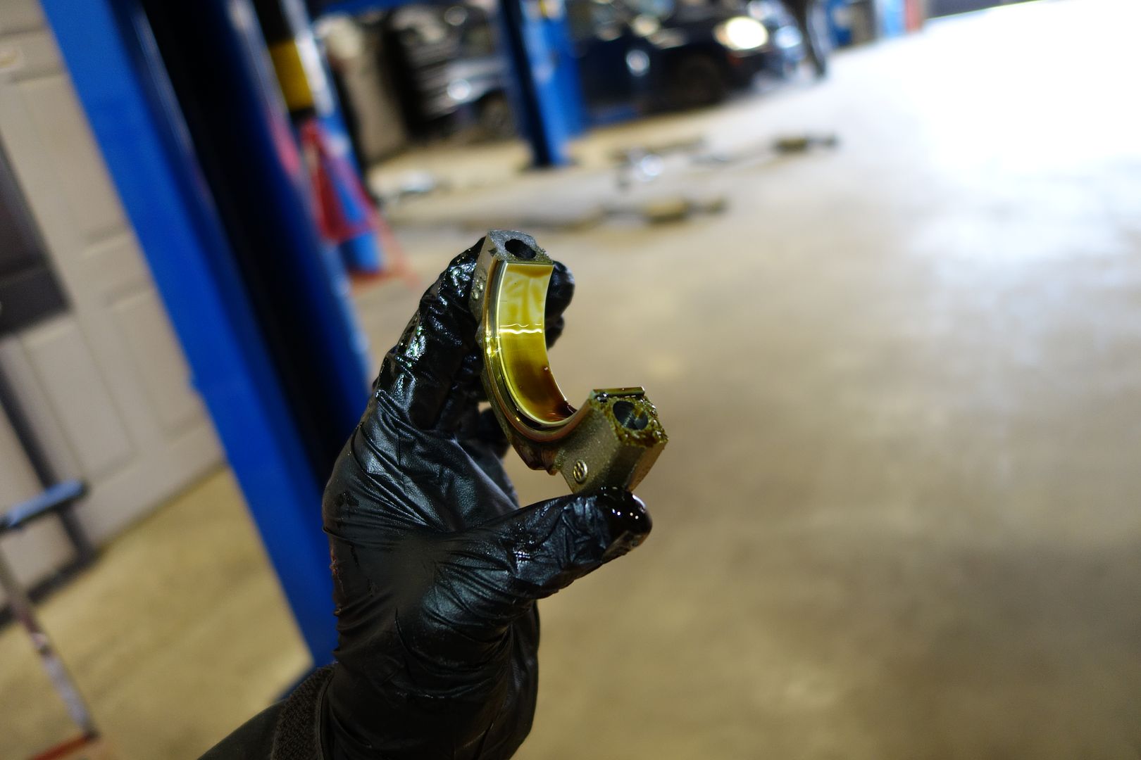
Journal looks happy
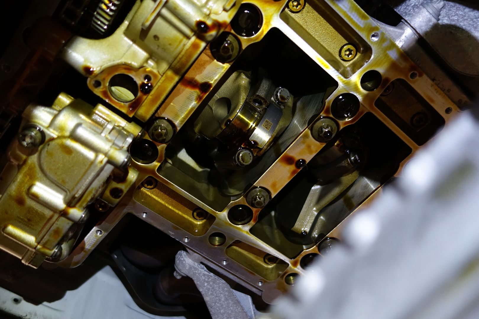
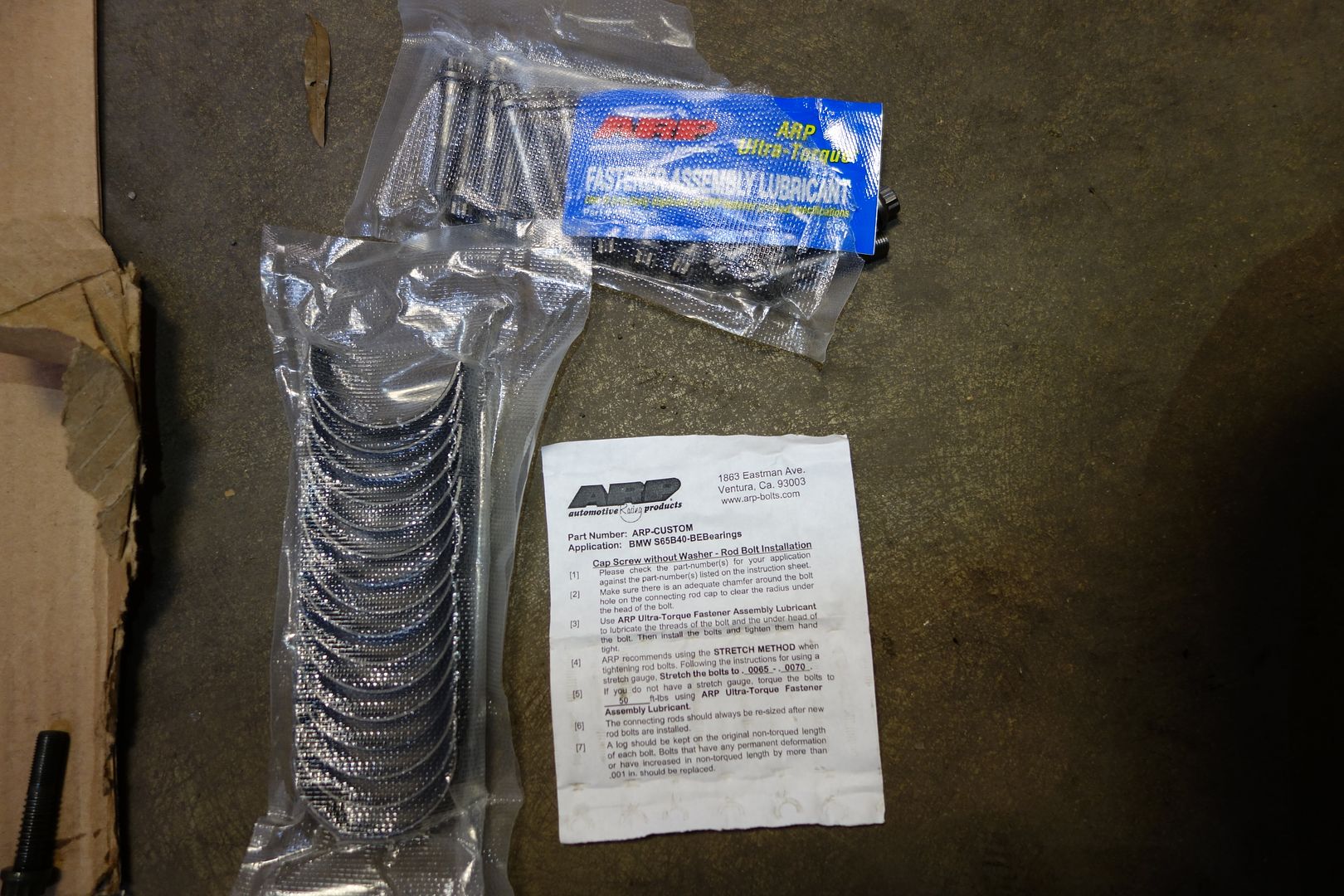
Here are my new goodies
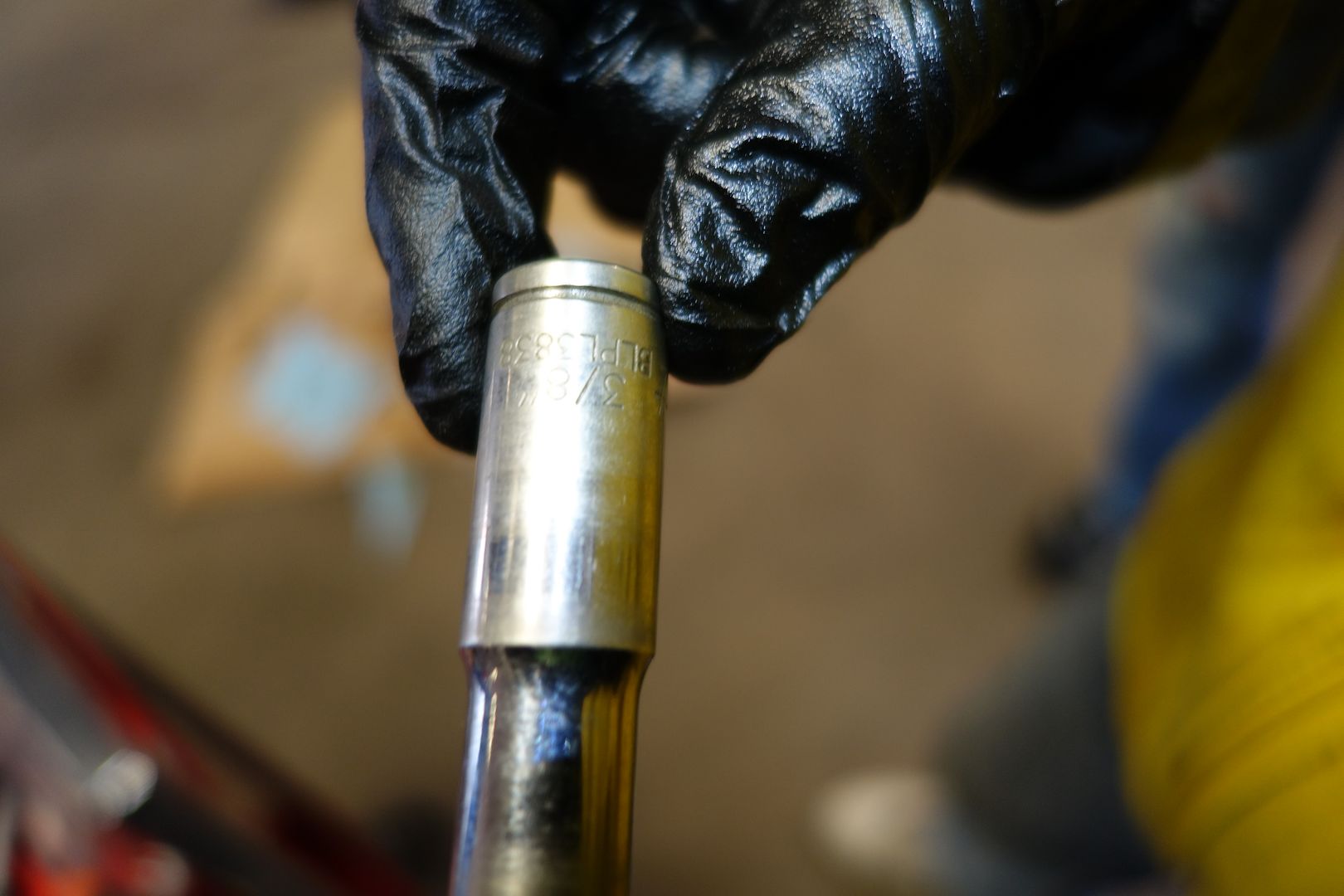
This is a pic of the socket you need for the ARP bolts
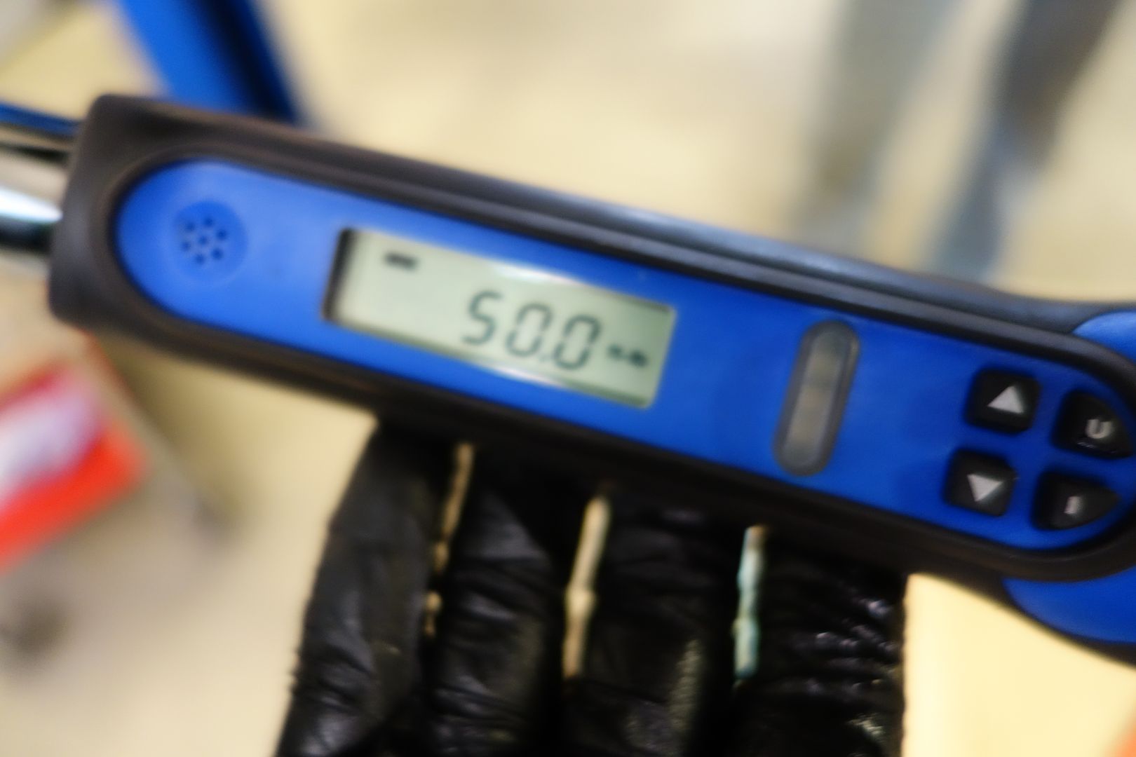
These are torqued to 50ft-lb. Note this entire DIY is in Nm except the rod bolts, which are made by ARP so they use an imperial fastener and imperial torque specs. First I torqued both sides to 30ft-lb, then to 50. I wanted to ensure they were well settled
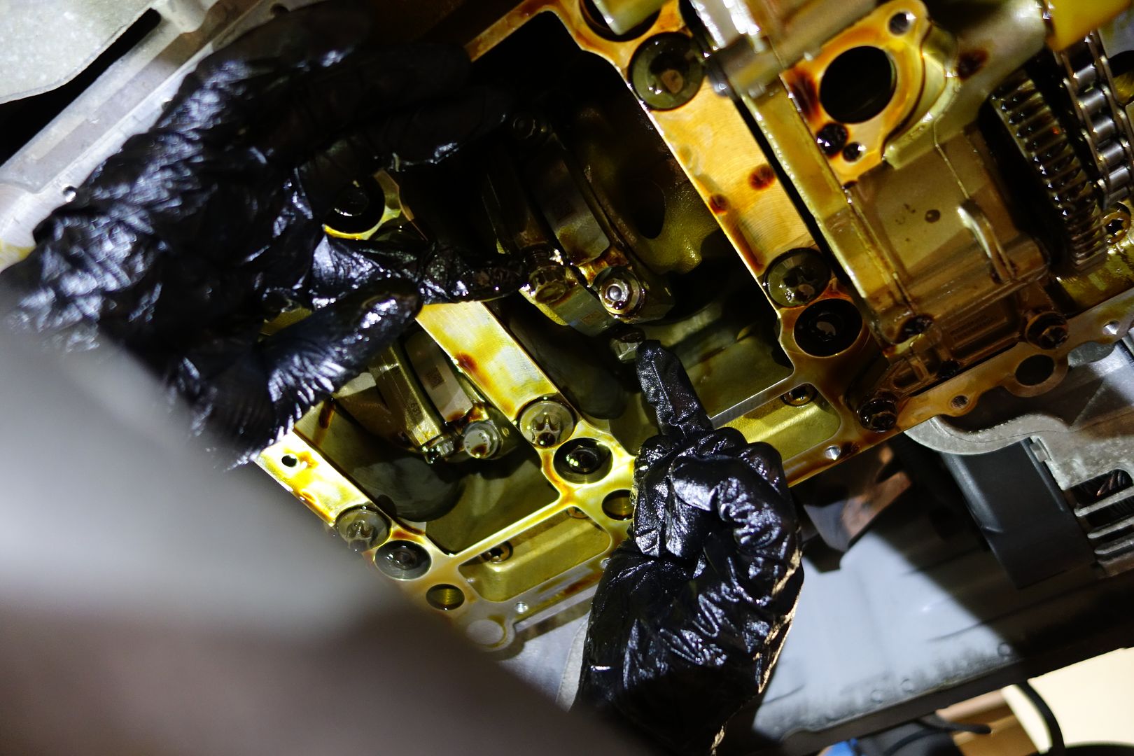
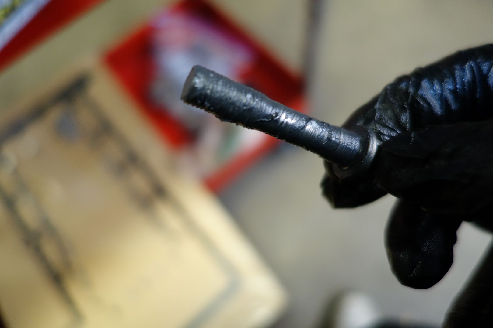
BE-ARP bolts come with lube. There’s like 20x the amount needed even though at the beginning I thought there was too little. You are supposed to cover the threads and head with lube as seen below
Plastigauge/Plastigage
I wanted to write this up because I’ve always been curious. As luck would have it, the massive box of plastigauge I had bought sometime in the past had every size known to man except the one I wanted. Nonetheless, I went through the procedure even though the numbers here don’t mean anything
You are supposed to use the new bearings here, but I used the old ones as the measurements in my case are worthless as I don’t have the right material
Note that the desired range when using green plastigage I linked above which is in inches is:
You should see anything from 0.0022 - 0.0028. Even the upper end of 0.0030 isn't the end of the world. The connecting rod bores seem to wear bigger over time.
For those that are on the upper end of the clearance spectrum that you'd like to bring down, get some 600-grit wet sandpaper, and sand the parting lines (with the paper wet). Go 6-8 swipes in each direction with light-to-medium pressure (5lbs - 10lbs pressure). Clean the dust thorougly, re-install, and re-measure. If it's still not where you want it, do it one more time. I don't think I'd do it more than twice though.
First you lay a little piece of plastigauge across the belly of the rod bearing
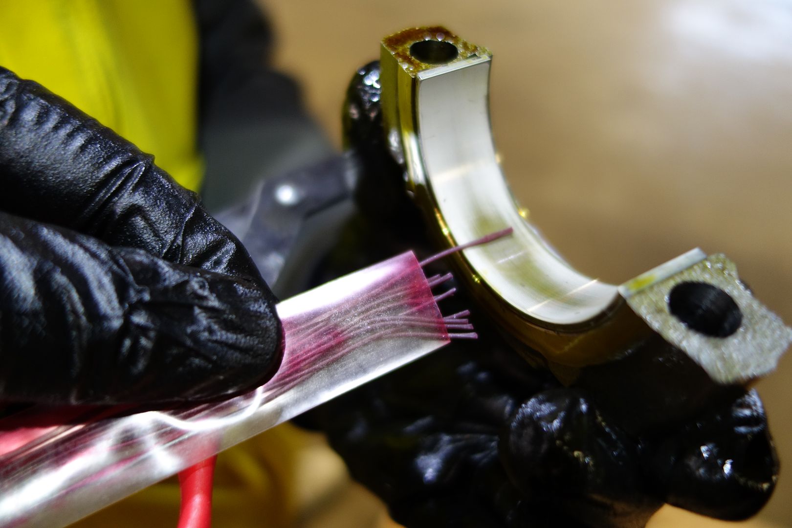

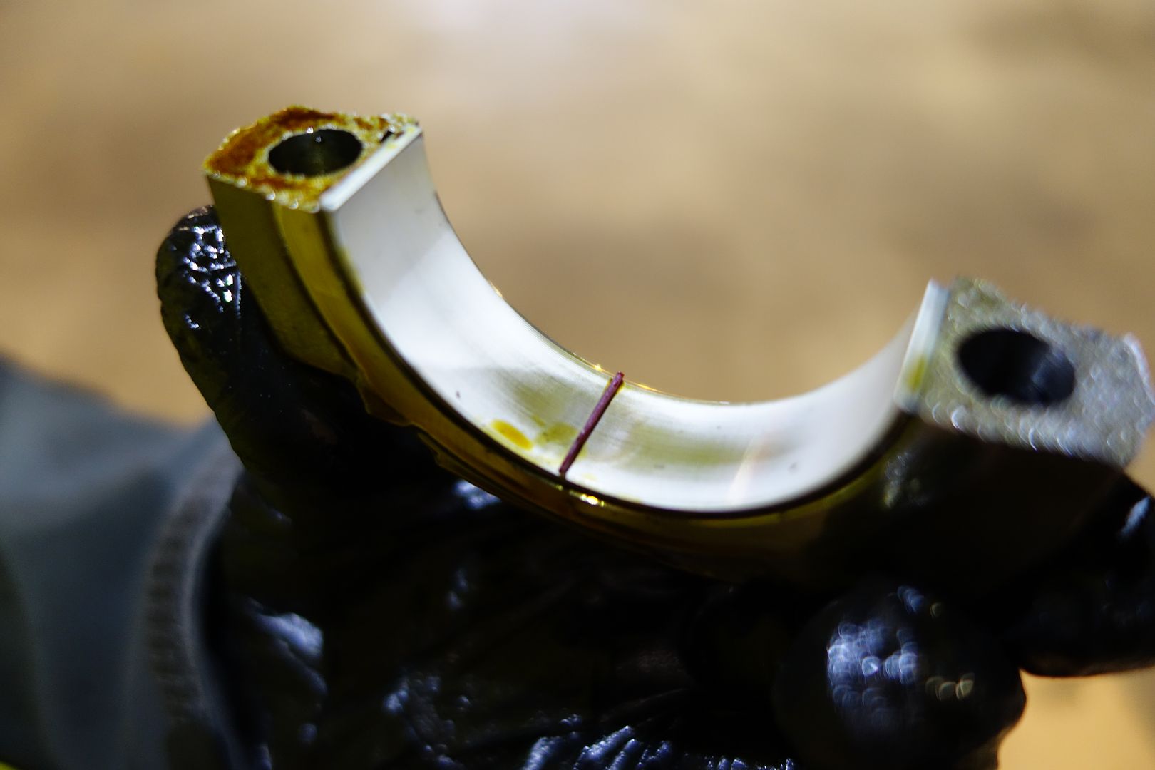
Then, you torque it down to whatever the fastener you use takes. Again, I used the old fasteners and tightened to 30ft-lb because my sizes were wrong
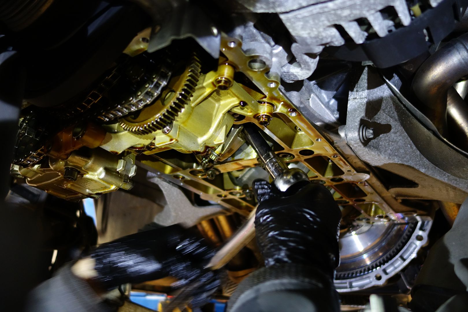
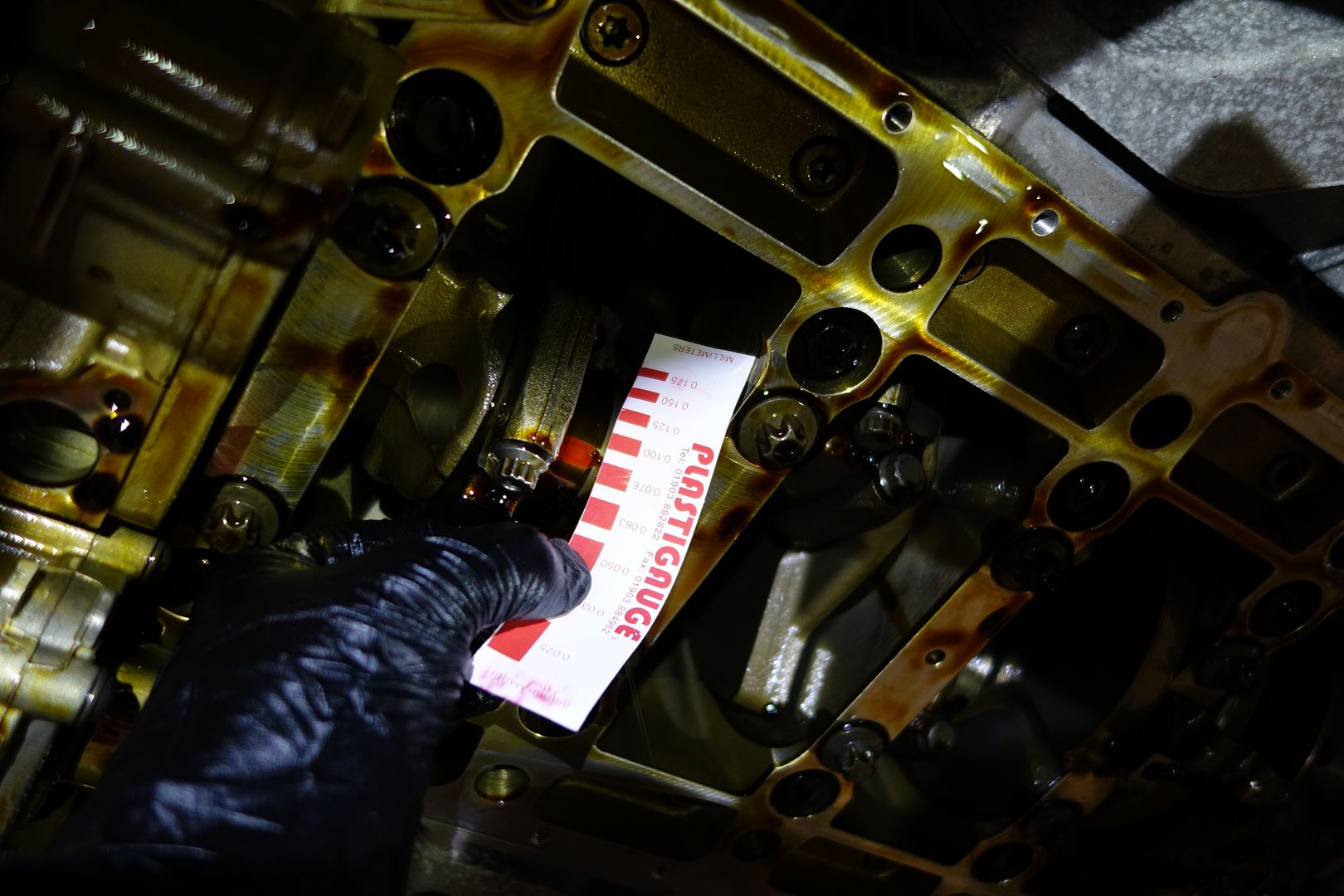
Finally, you remove the cap again and then compare against the piece of paper that comes with the plastigauge
According to this, I have 0.0076mm of clearance
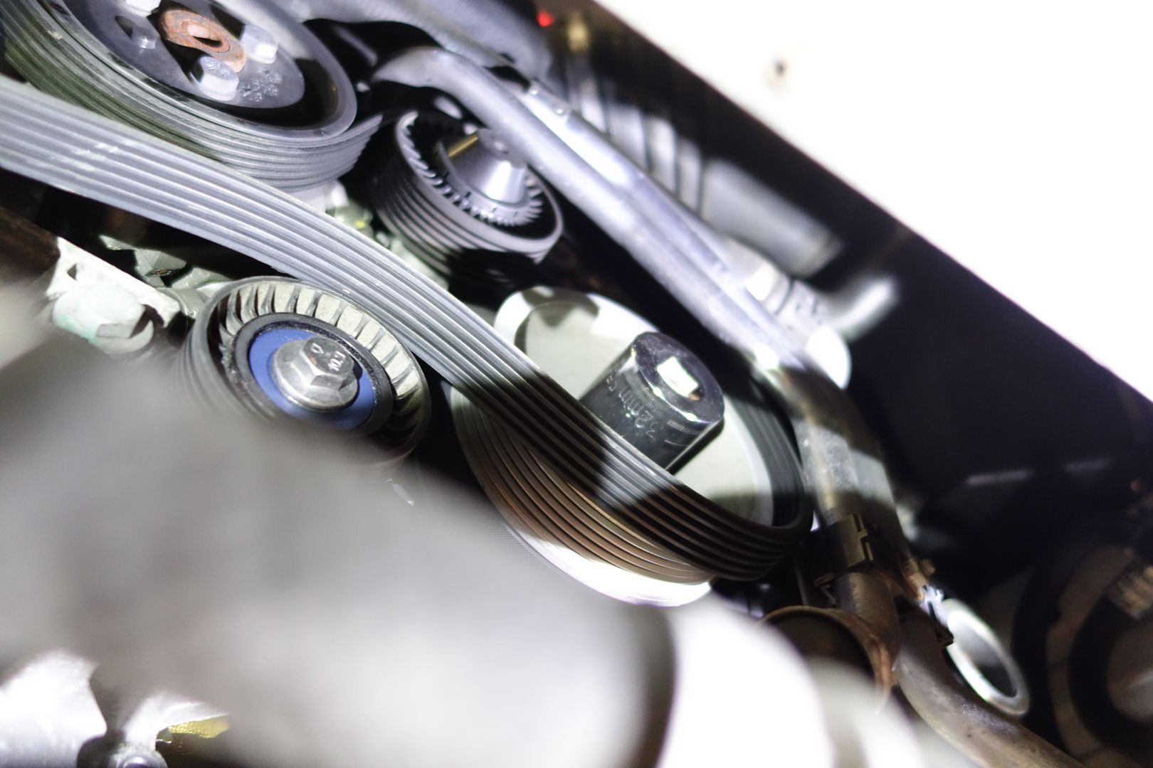
After the first two rods you’ll have to move to the third and fourth. You need to rotate the engine. You do this with a 32mm socket at the front of the engine and turn clockwise
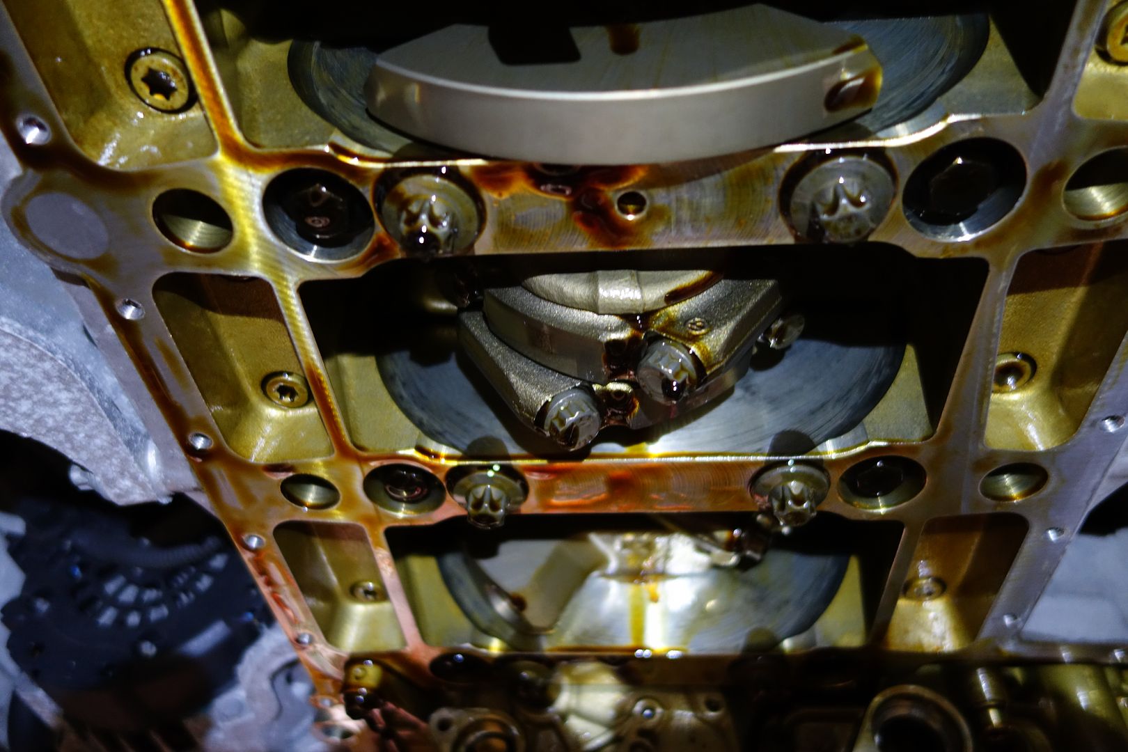
Eventually the third and fourth rods with be right in the middle and you can work on those. Repeat the process until you’re done
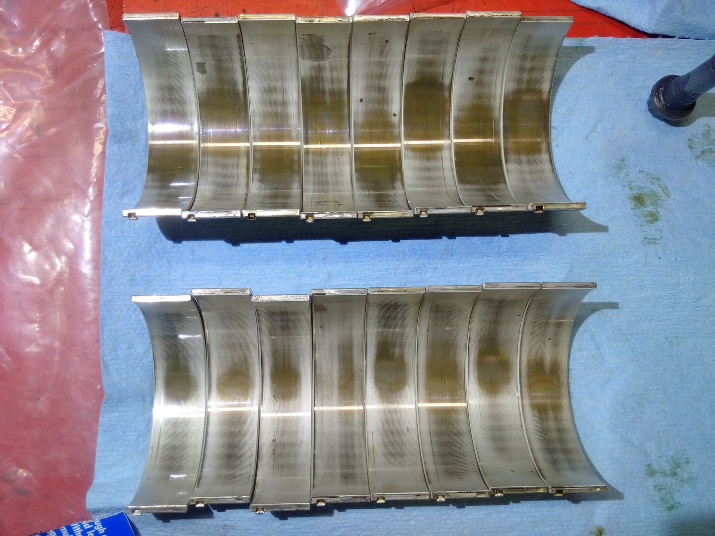
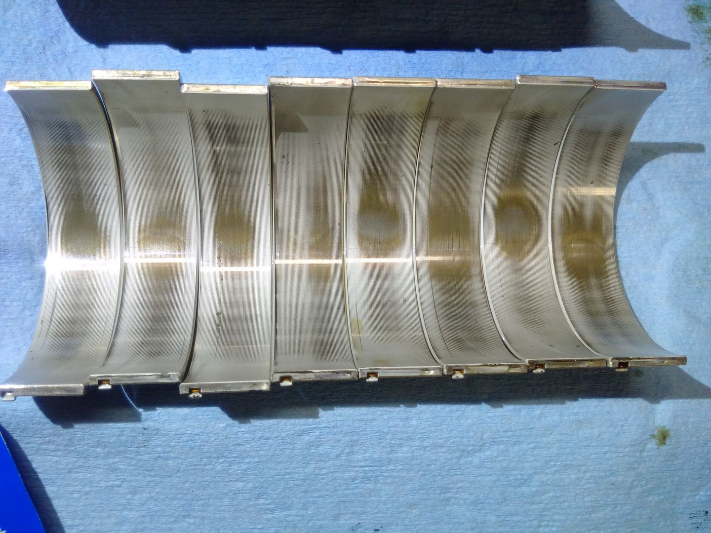
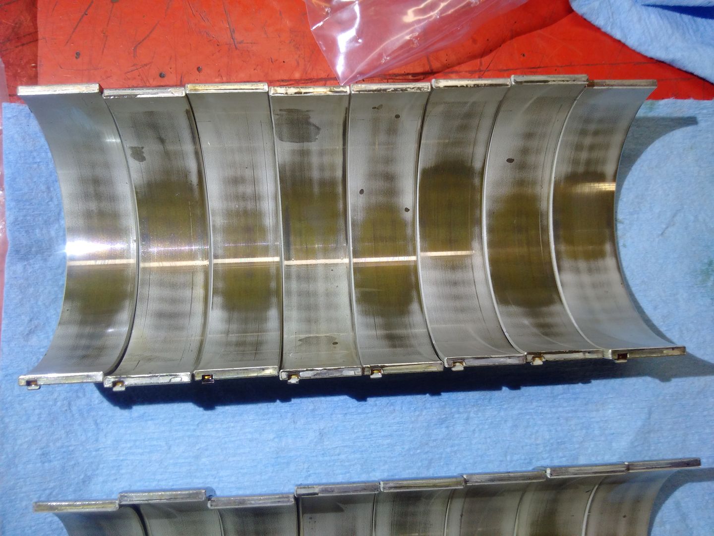
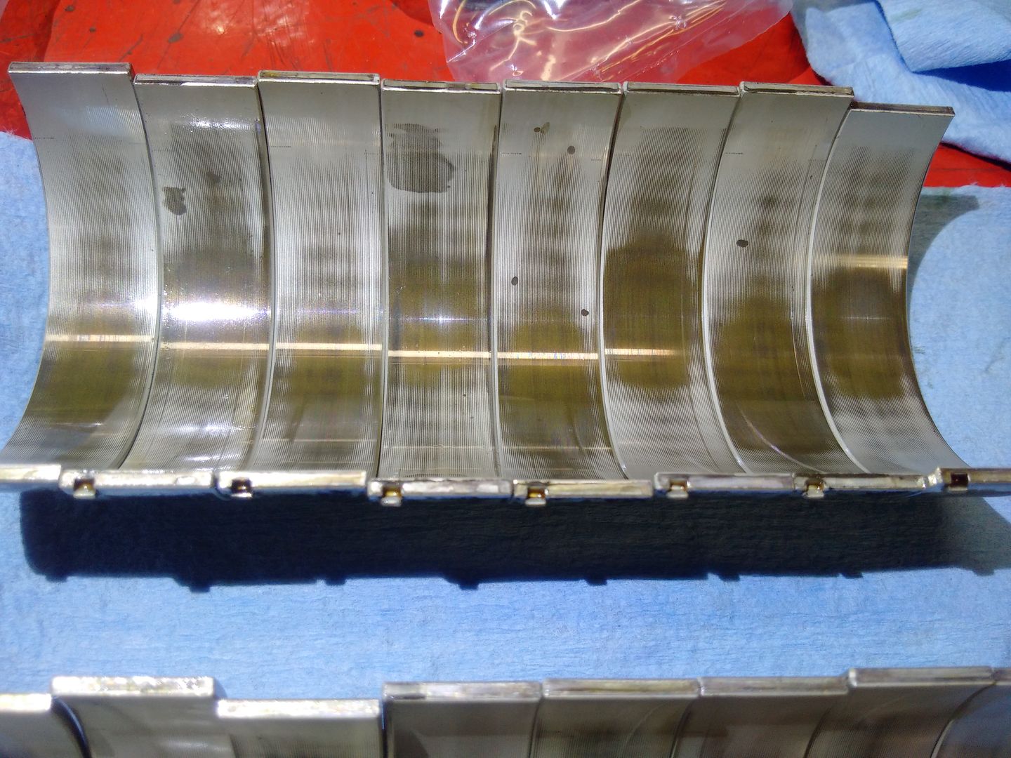
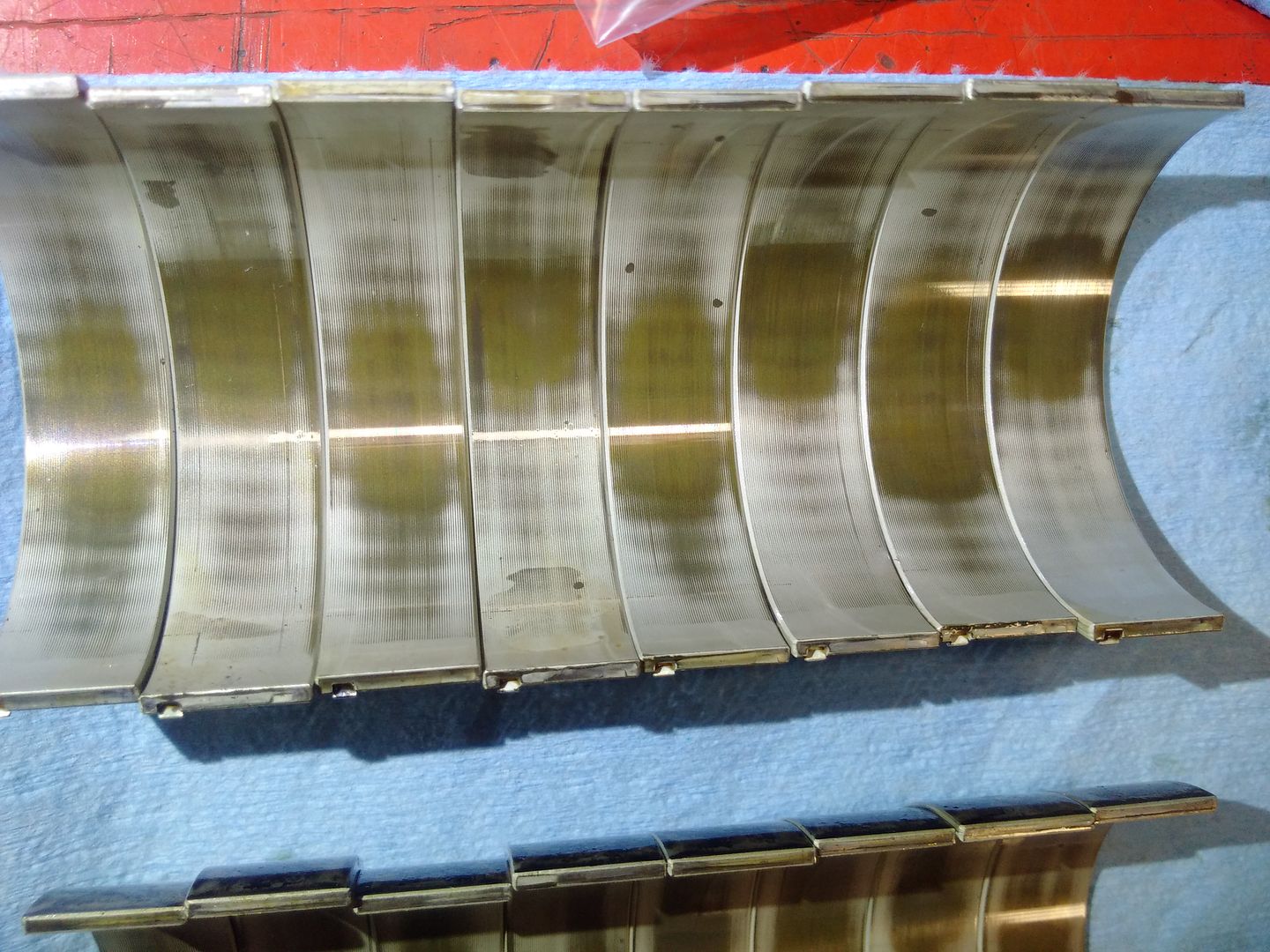
Lets see what the bearings look like!
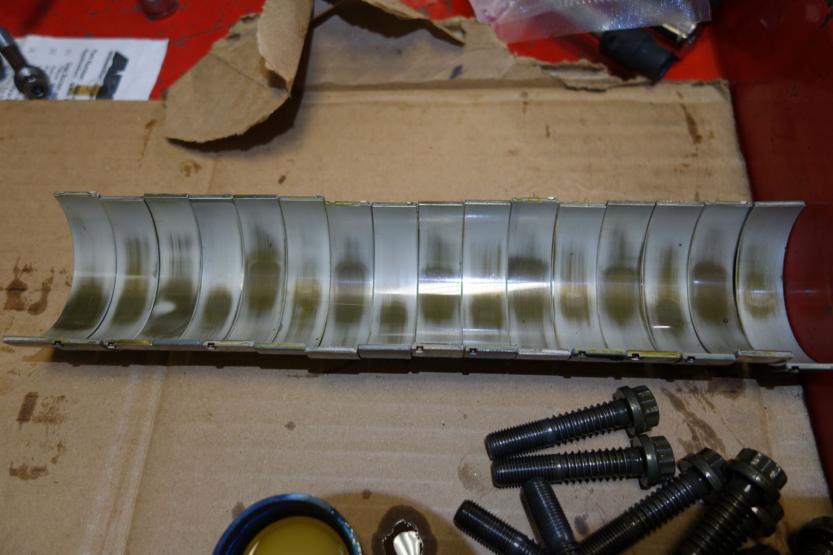
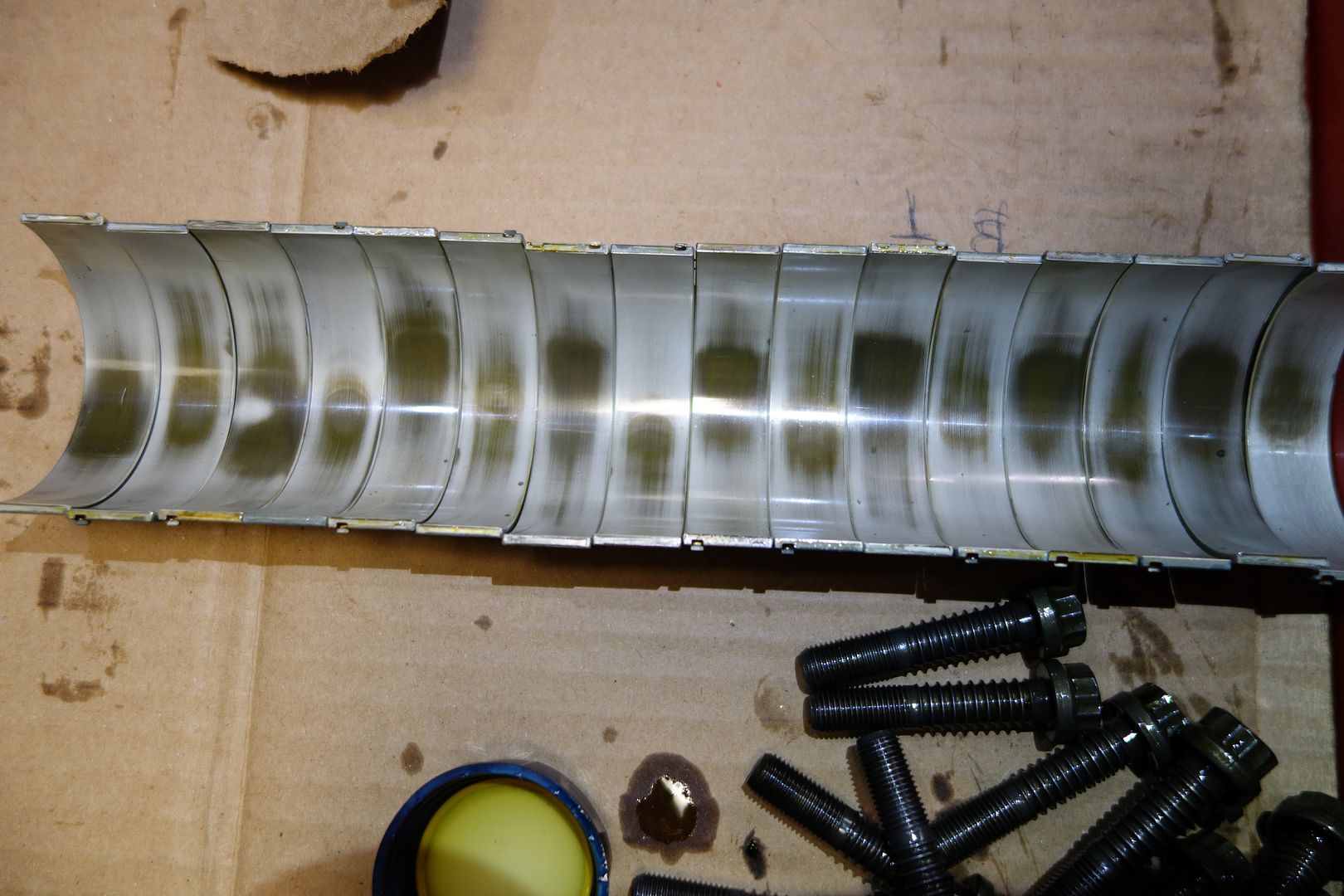
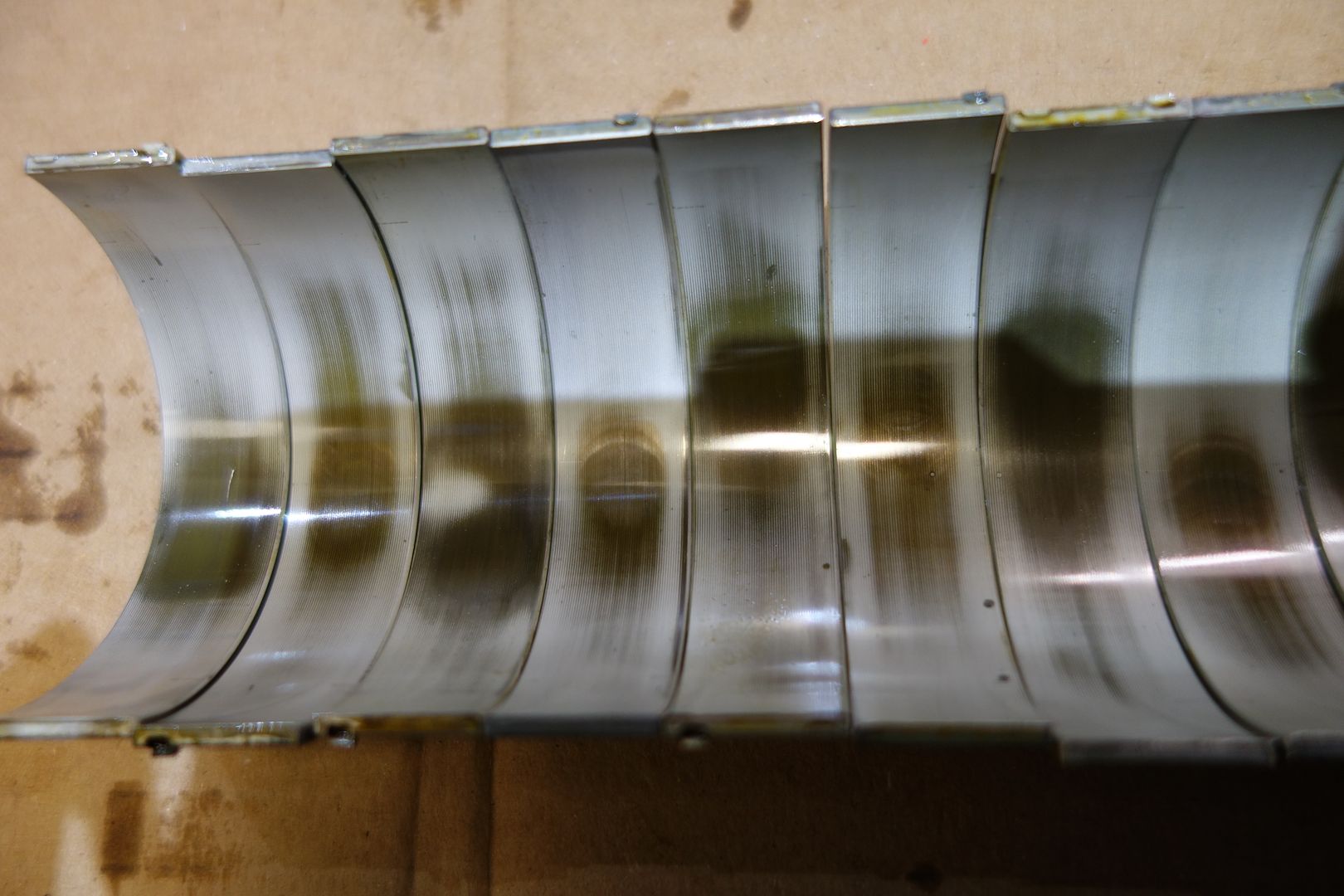
[URL=http://s1186.photobucket.com/user/SYT_Shadow/media/S65%20E90%20E92%20M3%20Rod%20Bearing%20DIY
/DSC01021.jpg.html]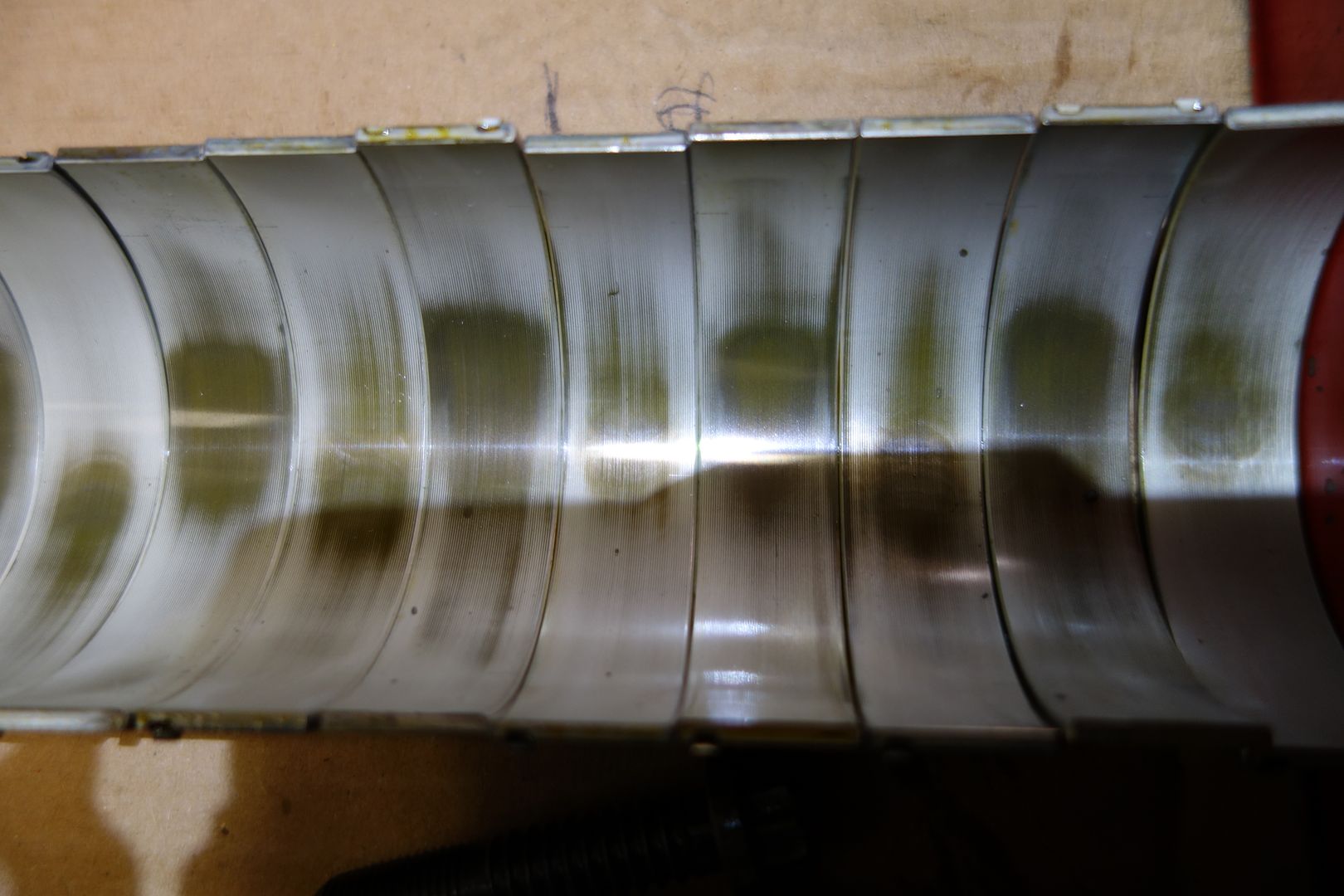 [/URL]
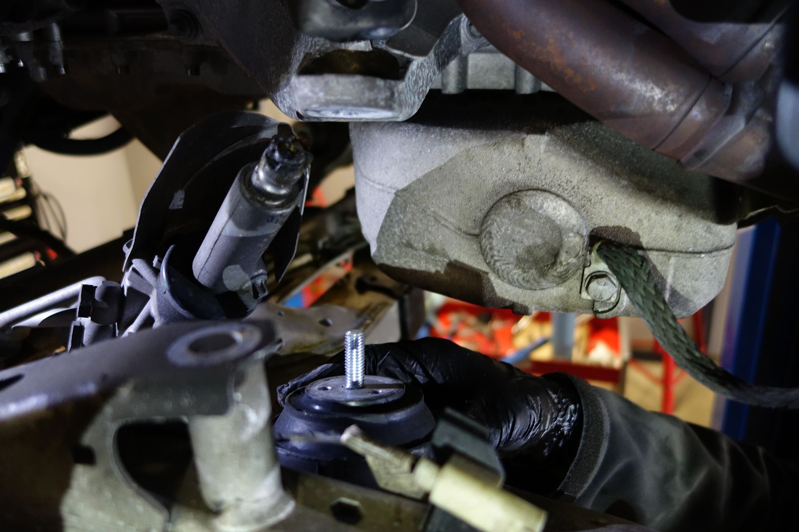
I also removed the engine mounts and swapped them for BW units. Note that after only 36k miles mine were not looking too hot
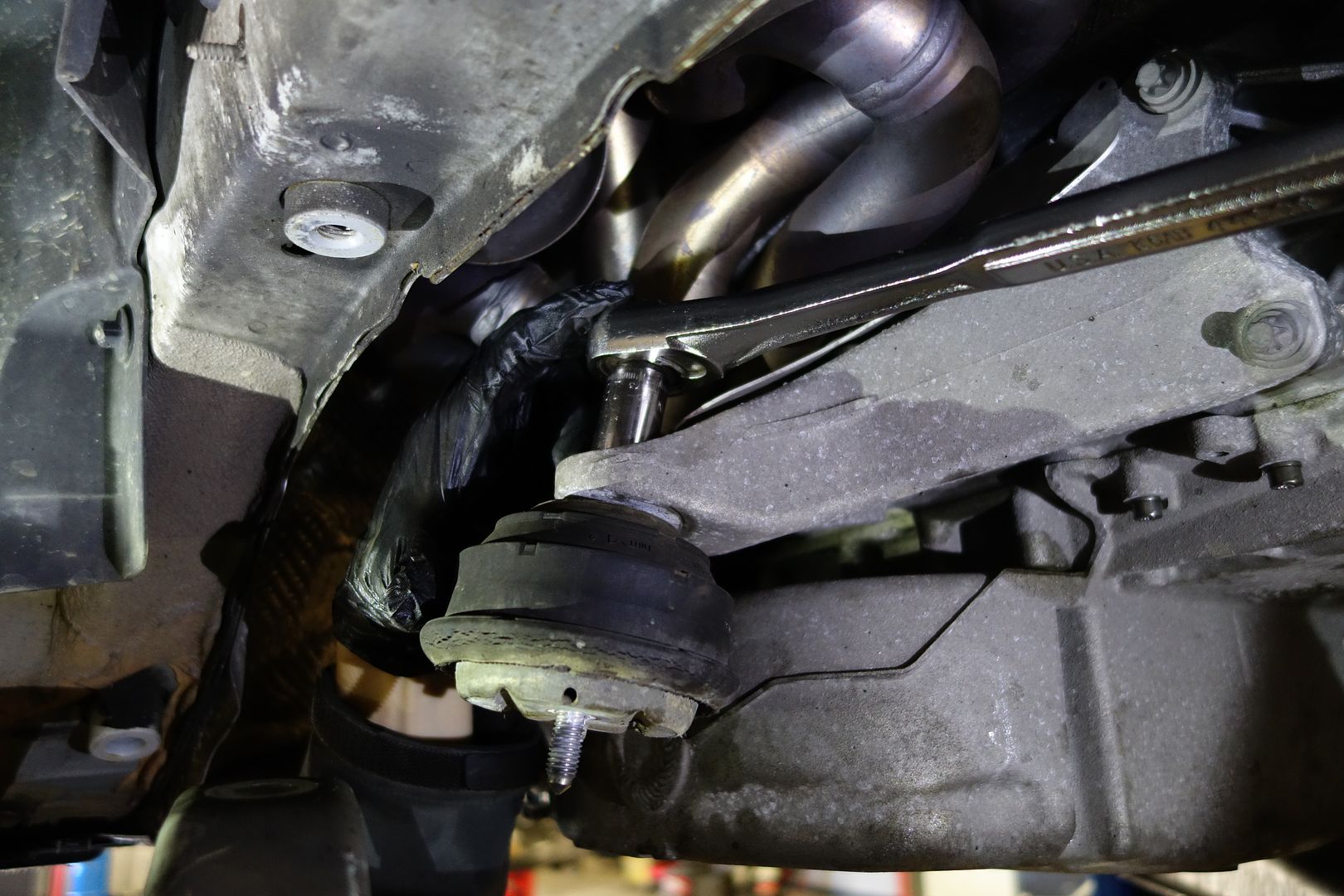
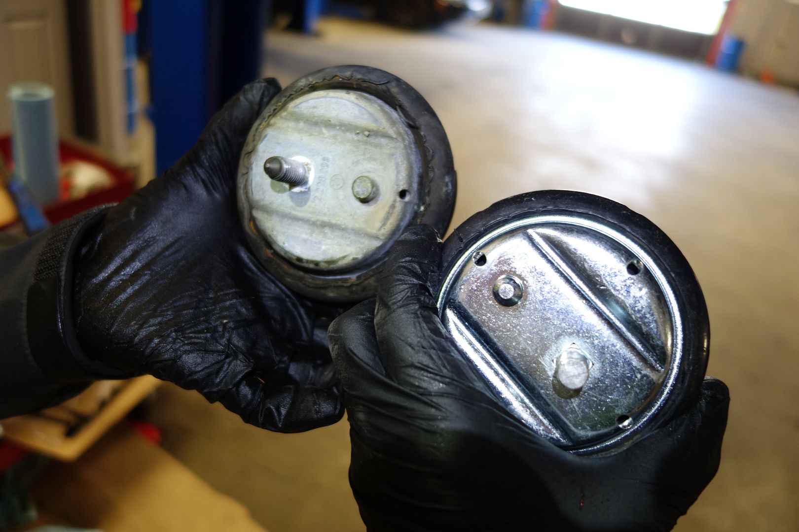
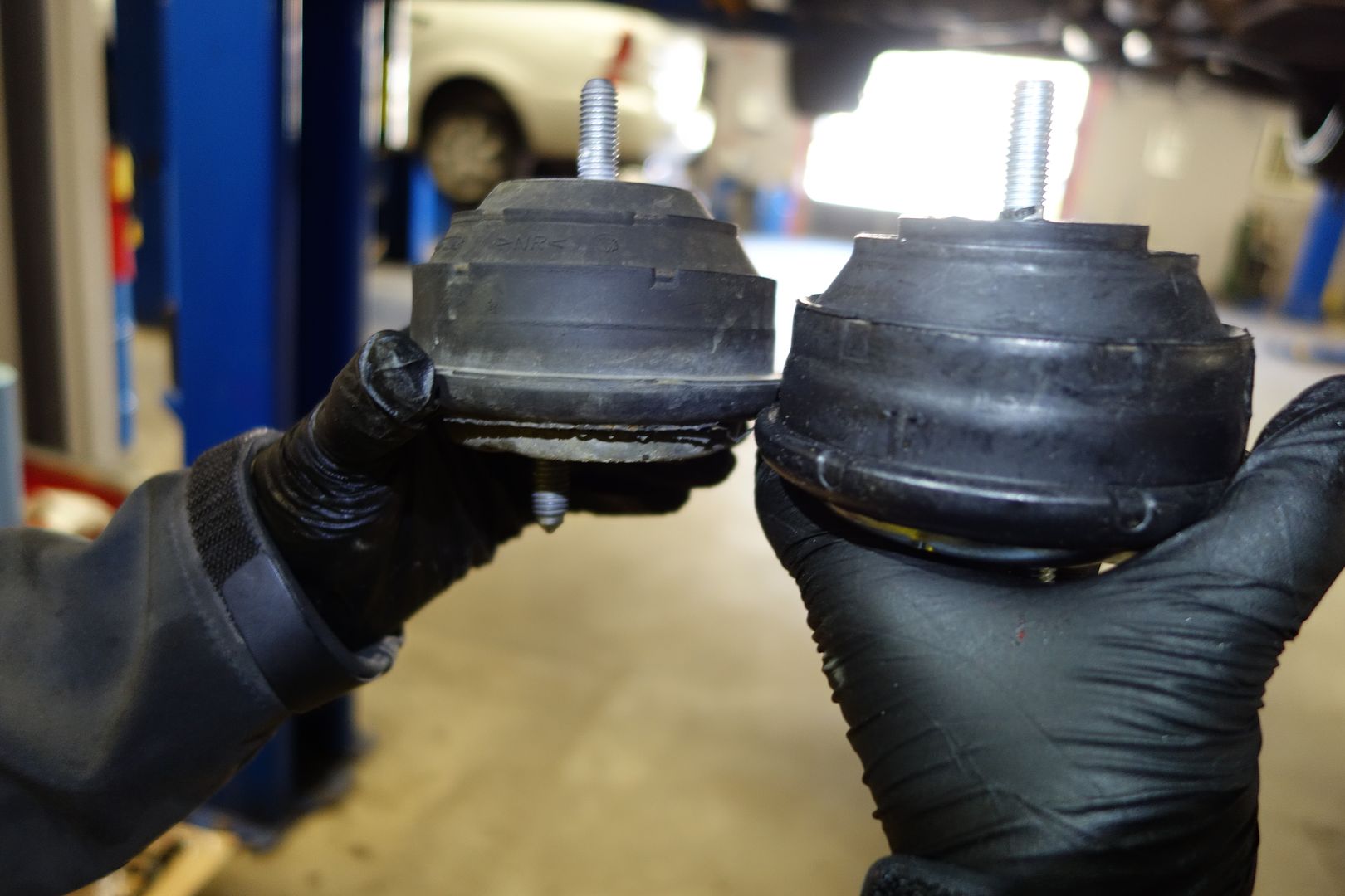
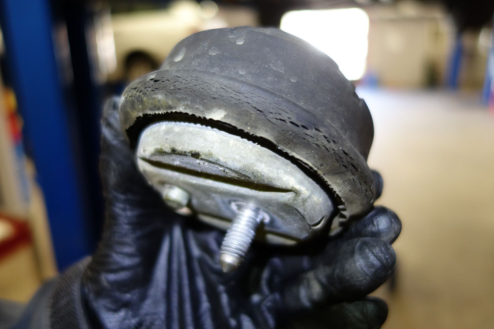
When reinstalling, you bolt the engine mount to the subframe instead of to the engine cradle where it just was
 1029
1029
Installation is the reverse of disassembly, but just in case I show the steering rack which is the hardest part. Start raising the subframe slowly and the parts will more or less mate up
Note you should reapply green loctite to the steering rack bolt before reassembling
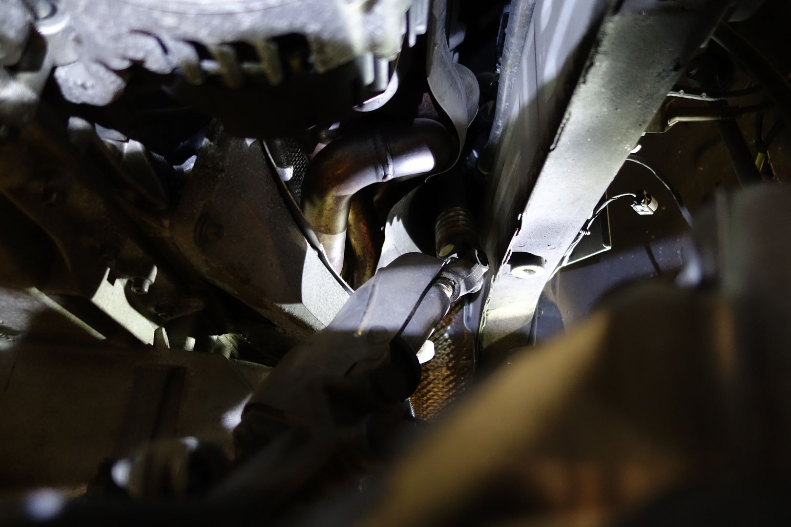

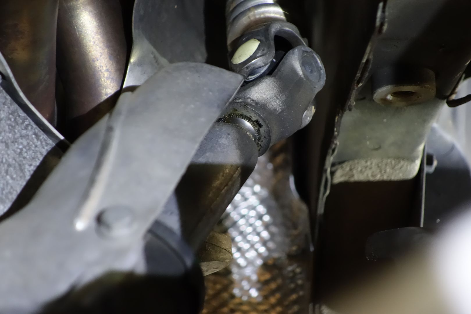

Don’t forget to fill up with oil and change the oil filter before turning the engine on!

Disclaimer
This DIY project is purely “at your own risk”. As with any DIY project, unfamiliarity with the tools and process can be dangerous. Posts should be construed as theoretical advice only.
If you are at all uncomfortable or inexperienced working on these projects (especially but not limited to electronics and mechanical), please reconsider doing the job yourself. It is very possible on any DIY project to damage your engine, vehicle, void your car's warranty, create a hazardous condition, or harm or even kill yourself or others.
The patient
2011 E90 M3 DCT purchased with 36k miles a couple months ago. It is a stripper car with DCT as the sole option… in other words cloth seats, no nav, slicktop! It is destined for the track in the 2017 season. The first step is fixing the bearings!
Special tools used
3/8” 12 point socket to install the BE-ARP bolts
6 inch T30. I had a 4 inch one and it doesn’t work, so I lost an hour driving around looking for one. Do not start the work without one!
To remove the OEM rod bolts you can use a 12 point 12mm socket.
Special hardware used
BW street/track (Group N) engine mounts. If yours is a street car, I suggest replacing them with OEM items
BE Bearings. I don’t understand why anyone would use something else
BE-ARP bolts. Again, these should be the default choice for everyone. Besides being the best bolts for these engines, you do not want to be angle torqueing stuff in this tight a space. Somewhere, someone is thinking ‘$500 is a lot for bolts’. Well good luck with that...
Plastigauge. You need the green one. You can buy some at www.summitracing.com/search/product-line/clevite-77-plastigage
Two different Computorq3 electronic torque wrenches. I have the ½” one as well as the ¼”, which covers the range of required torque. To do this with a crappy/inaccurate torque wrench is a waste of time.
Harbor Freight Engine hoist. I used this on my E46M3 rod bearing DIY. It’s a cheap piece of hardware that works exactly as designed!
Snap-on 3/8 electric ratchet. This makes everything a lot easier. There are a TON of bolts you have to remove to do this job, I highly suggest either this or the Milwaukee one
Time taken
This took 12h, first time doing it. We usually are slow workers. It was 10h one day and 2h the next. There is no doubt that if we were not doing a DIY - which requires you to spend lots of time pausing to take pictures, etc and renders one of the two people working useless - it would have taken significantly less. There was also one snag with the 4” T30 and subsequent easter egg hunt which took time, but you get the idea.
Torque specs (courtesy of E92love)
oil pan bolts (30 qt) and all other M6 bolts inside/outside engine: 10 Nm
steering rack bolt on step 6 (1 qt) (M8): 21 Nm
E12 transmission to oil pan bolts (4 qt) (M10): 38 Nm
engine mount nuts. 1 top, 1 bottom on each side: 56 Nm
the 6 front subframe bolts (M12): 108 Nm
rear 2 most subframe bolts (M10): 56 Nm + 90 degree
re-enforcement plate bolts (7 qt) (M10): 56 Nm + 90 degree
4 water pump pulley bolts (M6): 10 Nm
pulley tensioning system on both sides. 2 for each side (M8): 19 Nm
Part numbers (courtesy of ///Mobbin)
---bolded part = essential---
11137841085 - e92 m3 oil pan gasket
Oil pickup tube/system parts that I also ordered (just in case):
11417839832 - pickup tube o-ring
11417839833 - pickup tube o-ring
11417838534 - suction pipe gasket
11427837997 - oil filter kit (oil filter, o-rings, crush washers)
07119904550 x 2 - oil pan drain plug (includes crush washer also)
07-12-9-905-537 - 16 x oil pan screws
07-12-9-905-599 - 12 x oil pan screws
07-12-9-905-600 - 2 x oil pan screws
12611744292 - oil level sensor o-ring
11812283798 - engine mounts (might include nuts, not sure)
07119904025 x 4 - engine mount nuts
Acknowledgements
Kurt, Philip, Ryan, Bert&Ernie from BE Bearings. You can self-identify if you wish, but I sincerely appreciate your openness to being contacted for issues as well as the technical help from Bert&Ernie
Special mention to GearHeads International – which is paradise for the motor enthusiast! As many of you probably know, I no longer have a lift (or heated garage, for that matter) so in the northeast winters my capacity to do more complex DIY’s has seen itself a bit hampered… so I’ve been limiting myself to doing work on the cars outdoors. Well, no more!
For $150 a day, GearHeads in RI will rent you a climate-controlled bay with a lift and all the SnapOn & GearWrench tools known to mankind. It is such an impressive place! Ron, the owner, is always there (yes, 7 days a week) and is really nice. I am sure I’ll be back!
Ron is a mechanic and he swings by to see how you’re doing and is always willing to lend you a hand. I could not have been more impressed!
GearHeads allows you to live in an apartment and still access tools and a garage to install your suspension, supercharger, rod bearings, all those critical projects. You no longer have any excuses!
Note 1
As you will drain the oil you will need to refill it. A typical oil change in this car is 8 quarts/liters and a little more. While changing rod bearings you remove a massive amount of oil which would typically never leave the engine, which means you will need 9.5 bottles to fill it back up so the car is happy. Protip: have more than that just in case!
Note 2
At times the DIY pics will show something I haven’t explained yet, so it may seem out of order. That is because at times you try different things. You should follow the order of instructions explained here
Note 3
Rod bearings do not require break in. If you used assembly lube, you should change the oil after a few thousand miles. Both BE Bearings and Bimmerworld were contacted to weigh in on this. When you think of it, a rod bearing should never have contact with the crank. Regular break in is more about seating the rings and walls than anything else
Note 4
If you have a Dinan underpulley set you'll need to rotate the engine through the alternator. It can be done counterclockwise.
The patient
Putting the DCT into neutral. The 6MT guys can skip this part
Lift the shift boot from the front by pressing rearwards and unclipping it
There is a black guard which you can see in this pic. With a screwdriver, move to forward and it will slide out of the way
Here you can see the white lever that hides behind the black guard. You put a screwdriver in there and move it. The car will go into neutral and you'll hear a dong complaiingn about it
Install your engine support brace. Here are some pics of mine. You need to slightly tension it ‘upwards’ so that it is trying to pull the engine up, just a little bit. Remember the engine mounts are still installed so the engine cannot move much
I try to minimize potential energy, so I put a cushioned mat on top of the sharp parts of the engine support bar and then rest the hood on it
Remove the front wheels
We remove all the black felt underbody panels. There are many, many little screws
Note the three rear ones of the front felt part are different than the rest
When you remove the side front ‘wings’ you can see the cable structure that supports the front felt part. You slide the top sideways and then out so it falls freely. Note you don't need to remove the two screws that hold the bottom of those cables.
Continue removing the bottom felt pieces
More felt pieces
This is what you’re left with. Note the clips on the bottom of the fan which hold piping. Remove all the pipes from the clips
2Remove the aluminum chassis brace. There are 7 bolts, one of them is conveniently hidden inside the front center jack support
Remove the tranny felt underbody
A leaky DCT pan… wonderful… I’ll get to that sucker late[EDIT: replaced with Slonik/Slon Workshop DCT pan, incredible part!]
Go back to the top of the car
We now move onto the fan. I did the removal and reinstallation without removing any more of the air intake. It’s easier if you remove the air box, but it can be done like this
The radiator is held on by a single torx bolt on the passenger side. You can see it here. Remove it
Unclip the large connector right by the torx bolt
You can try sliding the fan upwards but it faces resistance. This is because there’s a clip that has to be undone on the driver side and the bottom of the fan has pipes clipped onto it
Lets go for the clip on the driver side, on the edge of the fan. You can just about put your arm in there and unclip it while you move the fan up. It’s a really tight, PITA fit but eventually you will release the whole fan after a lot of wiggling.
Peekaboo
Finally
Go back to the bottom of the car
Right by all the pipes you disconnected from the fan you have another ‘U’ pipe which is bolted onto the subframe. It has 3 bolts and one nut. One of the 3 bolts is shorter, that one goes on the passenger side of the rack
In the wheel well, remove the ABS/Brake lines from where they’re connected to the strut
Drain the oil. Remember there are two drain holes in the S65
Remove the front sway bar links. I see BMW learned from the bad design of the E46M and now you can use two regular open ended wrenches
The next thing in the way of lowering the oil pan is the belt tensioner. It is half attached to the engine and the oil pan, so we need to loosen it.
As it’s the tensioner it’s very hard to move and we must remove the belt first
Start by taking off the cap to access the bolt underneath. This is what we’ll use to release tension and remove the belt
EDIT: you can remove the belt tensioner once the subframe is out of the way. It's easier.
You then use a wrench to release the tension on the belt and slide the belt off. Once the belt is off, release the tension slowly until the tensioner reaches the end of its travel
Here you see the base of the tensioner which is still out of our reach because the subframe prevents us from reaching the bolts. Once we lower the subframe a bit we’ll return
Prepare to start undoing lowering the subframe.
First we unclip different wires. Here you can see two different cables that must be disconnected. One is to the lower left and goes to the arm which controls the xenon position, the other is a white connector
Remove the ground from the engine block
There is a bracket on the front driver’s side of the car. It’s held on with two bolts. Remove them
Notice the wrench I’m holding
Rotate the steering rack towards the passenger. Do it slowly and you’ll be able to peek at the steering rack bolt that has to be removed. You see this looking from the driver’s side of the wheel well
You need a E10 for the steering rack. Before touching this, draw a couple of lines between both parts you will uncouple. This allows you to mate it up exactly as it was. This is not poke-yoke, so it’s possible to set it back up with a crooked steering wheel. If that were to happen to me, I’d just get the car aligned, it is not the end of the world. I drew two lines and was able to reattach it perfectly
Here you can see the two lines
You need an extension to get there
It’s out!
Now we are ready to loosen then lower the subframe. Lets get the 6 bolts first. Note at this point I unscrew the 6 bolts but without removing them. You could also just remove them, the subframe weighs nothing and will happily hang from the suspension
After making sure no cable is about to snap, I release the bolts completely
We can revisit the tensioner now that the subframe is a bit lower. Remove the three bolts
Go to the back of the oil pan where there’s a surprising amount of cables. Unclip them and release the harnesses
It’s time for the oil pan bolts! Please take note of how long the T30 needed is. I used a 6 inch one because the 4 inch 'extra long' one I had bought for this job was insufficient
Remove all the oil pan bolts. There are many of them. The ones you need the extra long T30 are in the back of the oil pan
I followed smart people’s advice and inserted the oil pan bolts into the cardboard part that comes with the new oil pan gasket. There are a few diagrams I made. Left is the front of the engine, right is the rear. I put the car behind some pictures to make it extra clear. Note the two different lengths of bolts that are used, so take note!
Just like in the E46M, the back of the oil pan/tranny interface has 4 long bolts that go into the oil pan. I used an open ended wrench on 3 of them as a regular socket doesn’t fit
After that, the oil pan just falls down a bit. An oil pipe and the subframe avoids it from going far
Here you can see the fat pipe in the front which is standing in the way of our progress
UPDATE: it's possible to remove the oil pan without removing this pipe. You just have to finesse the oil pan into the right position.
Time to remove that pipe. It’s held on with two screws and has a mini gasket. Remove the short fat pipe. Note that this pipe has threadlocker on it, so be sure to reapply blue threadlocker when reassembling
Now you can drop the oil pan further
Next up are the two remaining oil pipes plus the supports. Remove them all. Note that all this hardware has threadlocker on it, so be sure to reapply blue threadlocker when reassembling
Finally, we can start accessing the rod bearings!
Cylinder 1 (most to the front of the car) is in the perfect position. You can do rods 1 and 2 without rotating the engine.
I went cylinder by cylinder completing the work
After loosening the two bolts that hold a cap, sometimes you need to give it a little nudge with a rubber mallet
Note these are cracked forged rods which, besides being awesome, are cylinder and side specific. That means cylinder one’s cap only mates to cylinder one and the left side must go with the left side. I guess enough people screwed this up with the E46M3 that they started numbering the sides, so now one side of each rod and cap has numbers are the other doesn’t.
Once you have a cap in your hand, you remove the old bearing. Easiest way I've found to do that is rotating it from the belly sideways, if need be one way and the other, and it'll slide right out.
Next get a new bearing, insert it into the cap (it is a bit springy, but it does fit), note that top and bottom bearings are identical in my case. Some BE Bearing sets will be marked 'top' and 'bottom' shells, so if that is the case be sure to put the 'top' shell into the rod, the bottom into the cap. The ones I received were undesignated tops and bottoms and could be installed interchangeably
Then, get some clean oil or assembly lube and cover the surface of the bearing. I misplaced my assembly lube but apparently oil works just fine according to technical folks, so I used that. I used a clean glove to spread the oil on, replacing it every time it got dirty because I touched another surface
First insert the bearing on the cap (where you can see what you're doing, and practice doing it by feel only), then the rod. To access the upper bearing just push the piston up by the rod and then nudge the old bearing sideways to get it out, just like you did on the cap.
Cap 1 removed!
Journal looks happy
Here are my new goodies
This is a pic of the socket you need for the ARP bolts
These are torqued to 50ft-lb. Note this entire DIY is in Nm except the rod bolts, which are made by ARP so they use an imperial fastener and imperial torque specs. First I torqued both sides to 30ft-lb, then to 50. I wanted to ensure they were well settled
BE-ARP bolts come with lube. There’s like 20x the amount needed even though at the beginning I thought there was too little. You are supposed to cover the threads and head with lube as seen below
Plastigauge/Plastigage
I wanted to write this up because I’ve always been curious. As luck would have it, the massive box of plastigauge I had bought sometime in the past had every size known to man except the one I wanted. Nonetheless, I went through the procedure even though the numbers here don’t mean anything
You are supposed to use the new bearings here, but I used the old ones as the measurements in my case are worthless as I don’t have the right material
Note that the desired range when using green plastigage I linked above which is in inches is:
You should see anything from 0.0022 - 0.0028. Even the upper end of 0.0030 isn't the end of the world. The connecting rod bores seem to wear bigger over time.
For those that are on the upper end of the clearance spectrum that you'd like to bring down, get some 600-grit wet sandpaper, and sand the parting lines (with the paper wet). Go 6-8 swipes in each direction with light-to-medium pressure (5lbs - 10lbs pressure). Clean the dust thorougly, re-install, and re-measure. If it's still not where you want it, do it one more time. I don't think I'd do it more than twice though.
First you lay a little piece of plastigauge across the belly of the rod bearing
Then, you torque it down to whatever the fastener you use takes. Again, I used the old fasteners and tightened to 30ft-lb because my sizes were wrong
Finally, you remove the cap again and then compare against the piece of paper that comes with the plastigauge
According to this, I have 0.0076mm of clearance
After the first two rods you’ll have to move to the third and fourth. You need to rotate the engine. You do this with a 32mm socket at the front of the engine and turn clockwise
Eventually the third and fourth rods with be right in the middle and you can work on those. Repeat the process until you’re done
Lets see what the bearings look like!
[URL=http://s1186.photobucket.com/user/SYT_Shadow/media/S65%20E90%20E92%20M3%20Rod%20Bearing%20DIY
/DSC01021.jpg.html]
[/URL]I also removed the engine mounts and swapped them for BW units. Note that after only 36k miles mine were not looking too hot
When reinstalling, you bolt the engine mount to the subframe instead of to the engine cradle where it just was
1029Installation is the reverse of disassembly, but just in case I show the steering rack which is the hardest part. Start raising the subframe slowly and the parts will more or less mate up
Note you should reapply green loctite to the steering rack bolt before reassembling
Don’t forget to fill up with oil and change the oil filter before turning the engine on!


 Those suckers were on there and difficult to loosen. 38Nm is super light torque. I used the 'goodntight' torque values on all except the rod bolts. Snap on tech angle torque wrench buzzed me on every bolt. 10Nm may be correct for the oil pan bolts. Others feel really low. I'm not saying E92Love is wrong, just saying the torque values don't feel right to my 20years of this kind of wrenching calibrated hands. YMMV.
