

SaNGRia wroteI got lucky by finding an x1 2014 in a local junkyard 2hrs away....i ran the vin to see what it was equipped with and because the pdc module in question based on realoem is for x1equipped for 609 and 508 that x1 i found was equipped and bit the bullet and chanced it and when i got there it was still there and only paid $20for it and the hsd cable frm end from end to end as well as upto 15ft of the harness thats connected to trvsci requested this part from Europe since it looked out of production in USA. But the Ebay seller from Lithuania. You need to find a seller over there, they can most probably request the part!
460KVIEWS
375REPLIES
134APPRECIATES
08-10-2026LAST POST
breaker1369 wroteExcellentI got lucky by finding an x1 2014 in a local junkyard 2hrs away....i ran the vin to see what it was equipped with and because the pdc module in question based on realoem is for x1equipped for 609 and 508 that x1 i found was equipped and bit the bullet and chanced it and when i got there it was still there and only paid $20for it and the hsd cable frm end from end to end as well as upto 15ft of the harness thats connected to trvsc
SaNGRia wroteQuestion....for power couldnt i just use the wiring that supllied power to sat radio tuner to supply power to trsvcExcellent
Well got all wired up coded and all but still no image is being produced...inpa read trvsc module but when i go to menu i get the ifh 0009 no response from ecu...i have pro tools and it also is detected but when i go to its menu i get the same
breaker1369 wroteAnd your CIC is C1A?Well got all wired up coded and all but still no image is being produced...inpa read trvsc module but when i go to menu i get the ifh 0009 no response from ecu...i have pro tools and it also is detected but when i go to its menu i get the same
Yes sir
breaker1369 wroteWell if you cant get the image i would lookg for :Yes sir
FBAS Cable and CIC Fbas coding parameter first.
Would make sure PDC default coded
If you believe everything is in place and coding is right then i would be suspected one of the module being faulty!
SaNGRia wroteI hope not....that would suck and further delay my pending repainting car project...Well if you cant get the image i would lookg for :
FBAS Cable and CIC Fbas coding parameter first.
Would make sure PDC default coded
If you believe everything is in place and coding is right then i would be suspected one of the module being faulty!
Ncsexpert and inpa does recognize trsvc module and protools app as well and since i dont have the jbf3 module equipped i know i cant read it....cant in protools as well..
breaker1369 wrotewell u dont have to read the trsvc as i said. It always works out the box. U gotta check ur fbas cable and coding again!I hope not....that would suck and further delay my pending repainting car project...
Ncsexpert and inpa does recognize trsvc module and protools app as well and since i dont have the jbf3 module equipped i know i cant read it....cant in protools as well..
SaNGRia wroteOk now back tl this got a lil busy worh work havent had a chance to check wiring....but i do recall when during the ncsexpert process when i was updating Vehicle Order under expert mode which i assume is the profile to use when modifying vehicle order for borh cas and nfrm...i didnt change profiles to default code cic and pdc.....would that be possible issue?well u dont have to read the trsvc as i said. It always works out the box. U gotta check ur fbas cable and coding again!
breaker1369 wroteYes sir. If you want i can do remote coding to solve the issue! PM me!Ok now back tl this got a lil busy worh work havent had a chance to check wiring....but i do recall when during the ncsexpert process when i was updating Vehicle Order under expert mode which i assume is the profile to use when modifying vehicle order for borh cas and nfrm...i didnt change profiles to default code cic and pdc.....would that be possible issue?
SaNGRia wroteWill do..thank u....ill msg u by the end of the week once im finished with wrapping everything up in the interior and trunk lid, came up on a jbbf 3 h3 frm local junkyard had removed fuse block as well and kept jbbf 3 connected to it and guy at window only charged me $24 which is the price of the fuse block lol so ill be upgrading fuse block and jbbf, reconfigure MOST wiring, originally had ccc with tcu, mulf, sat, cd playter options equipped but when i upgaded to CIC with combox, CIC had sat built in and thought i'd clean up the MOST wiring by removing the lines for TCU, SAT and CD eleminating the need for MOST loops and reconfigure the MOST BLOCK only having line outputs for what i have left to feed signal which is only AMP, COMBOX and back to CIC up front... finish up trunk lid project, (doing the pre lci to lci rear end upgrade) cut the handle opening wider to fit an f series trunk handle with oem camera bracket and also since LCI versions did away with key lock cynlinder to open trunk with key ill be drilling out the opening to put key cylinder from my current trunk in place....murphys law i dont do it now and months down the road i end up closing trunk with disconnected battery and deal with that problem to gain access lol....and since i now have the pdc module that has input for front pdc sensors, ill be adding that as well...when i got the fuse block and jbbf3 the same car which is an 2011 e90 LCI , it was also equipped with front pdc's and grabbed all what that has to do with front pdc....but yeah should be done by end of the week....Yes sir. If you want i can do remote coding to solve the issue! PM me!
SaNGRia wroteJust wanted to check, the error code that comes up, is it visible on the iDrive or only when scanning with ISTA?This is a common issue. E84/E70 came with EBH3 module instead of DSC. For this reason TRSVC that is made for E84 and E7x series looking for EBH3 instead of DSC. Since E9x cars came with DSC there is nothing you can do. Just live with it

Thanks!
e34_lover wroteOnly INPA/ISTA!Just wanted to check, the error code that comes up, is it visible on the iDrive or only when scanning with ISTA?
Thanks!
Thank you Sangria for the brilliant write up. I did the camera handle a slightly different way that may be of interest to others.
Instead of cutting the handle, I filed down the metal body of the camera to fit the handle. The snug fit also means that the camera is just pushed into place. It is held firmly without any glue or sealant. I have now done ~1500km with the camera fitted (including ~20 Nurburgring laps) and the camera hasn't budged.
This is the handle I purchased from Amazon UK. It looks to be identical to the one Sangria used. If you are looking for a handle, just make sure it has the silicone boot covering the handle.
https://www.amazon.co.uk/gp/product/B07PHWC6DP/ref=ppx_yo_dt_b_search_asin_title?ie=UTF8&psc=1
This is the handle with its camera still fitted and the boot removed:
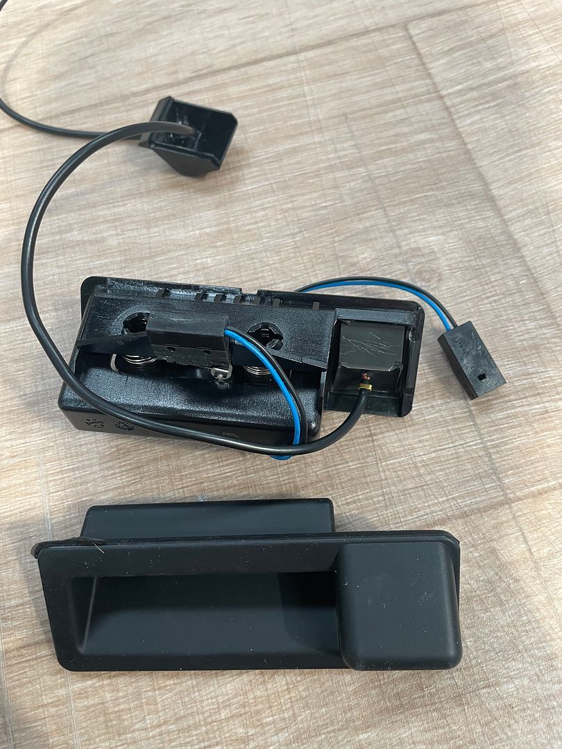
I dug out the camera from the handle. It came out easily considering it was glued in.
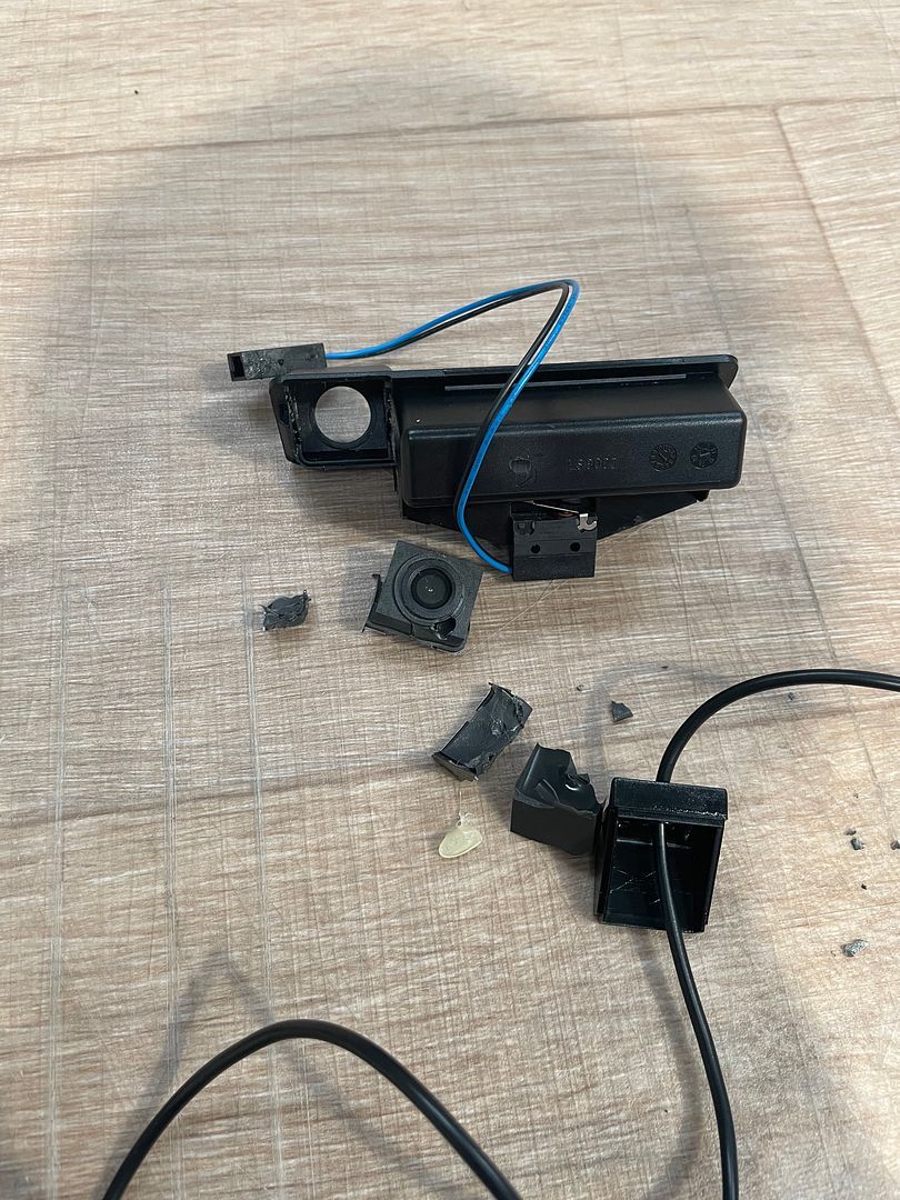
I then split the plastic surround off the F10 camera. I used a knife to cut along the weld line and then a flat head screwdriver to lever the halfs apart.:
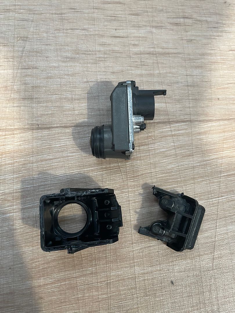
I then slowly filed down the body of the camera to make it fit. It took a lot of trial fitting to get it right. The big advantage is that I did not have to cut the handle, weakening it. I did fit away a bit inside the handle, but this was minor. This is how the camera looked when I was finished. I did not go all the way through the housing or seals anywhere so it is still watertight:
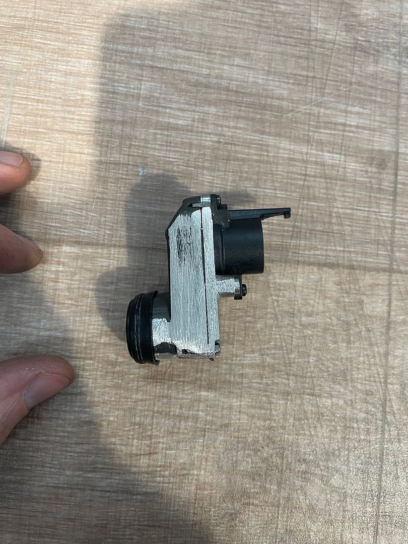
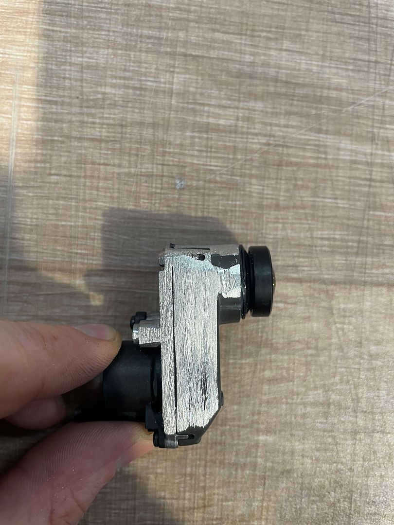
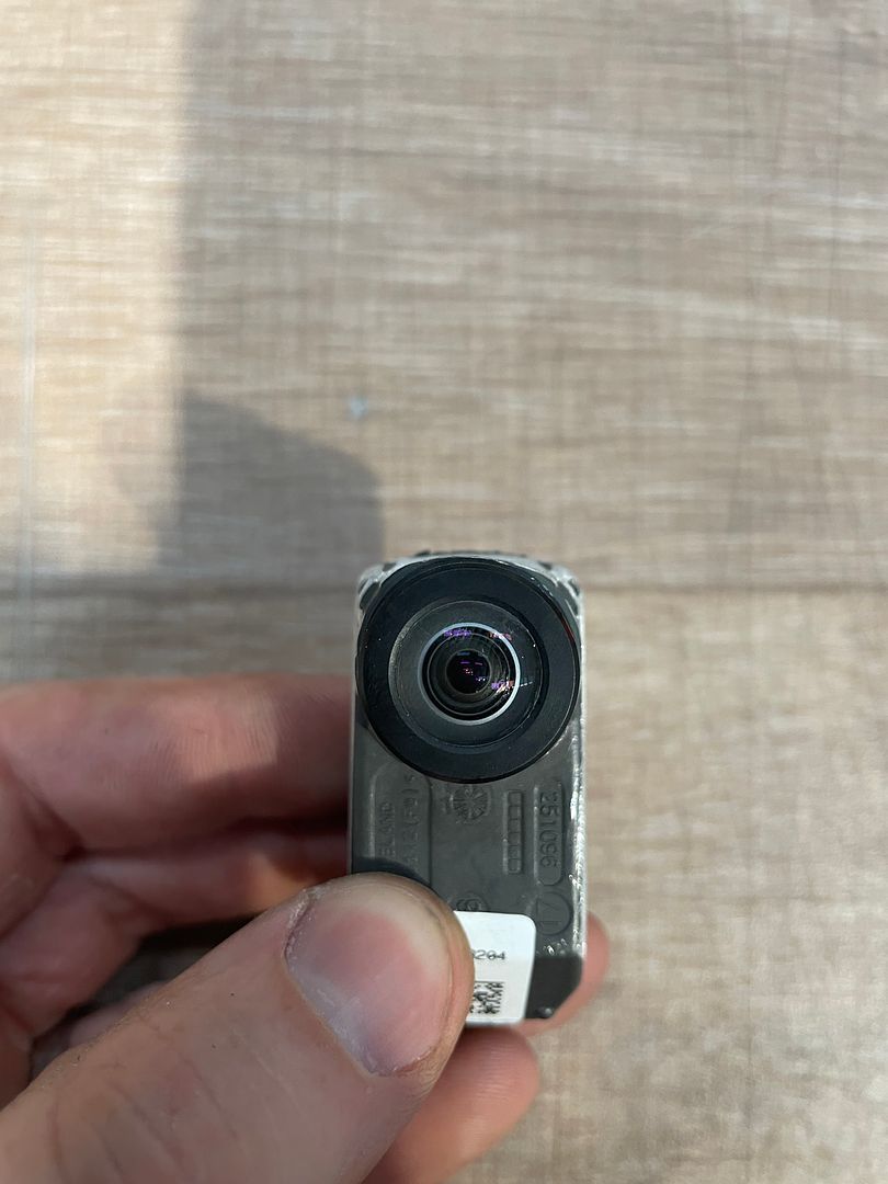
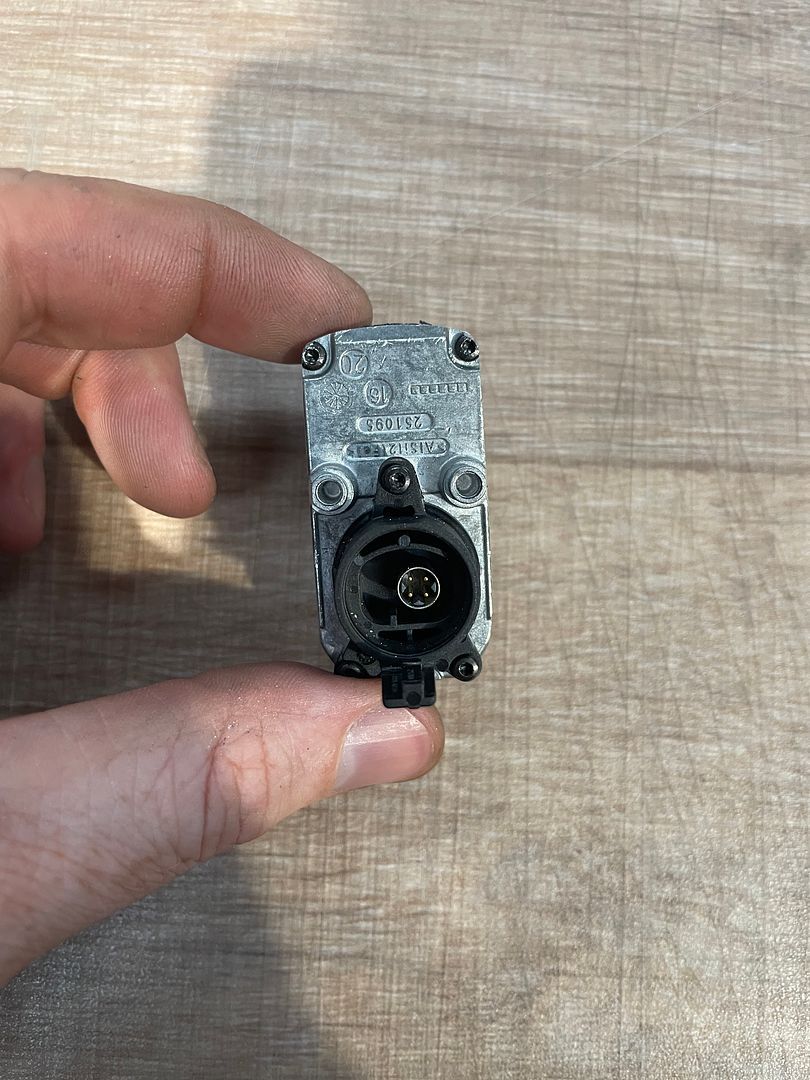
This is the small bit of sanding I did to the handle:
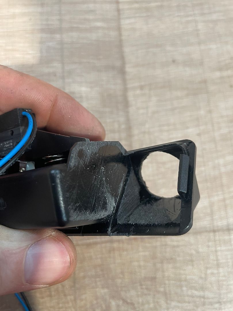
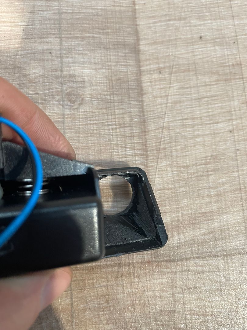
And the finished job:
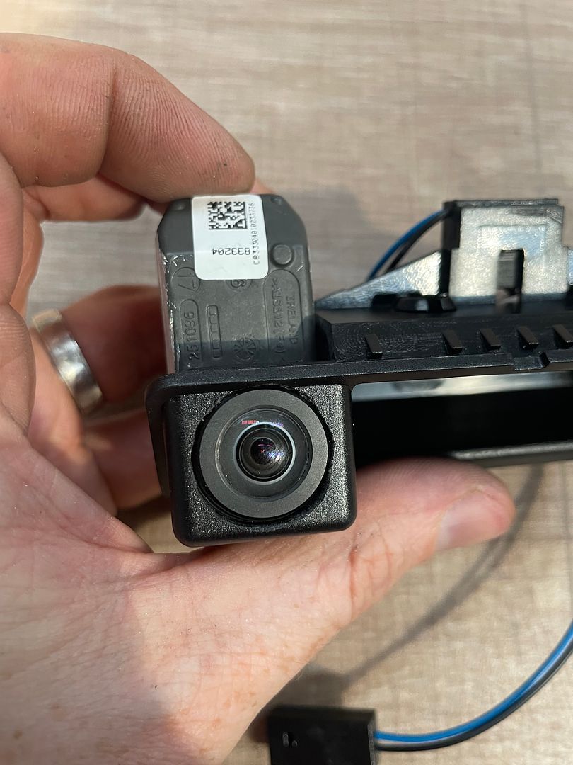
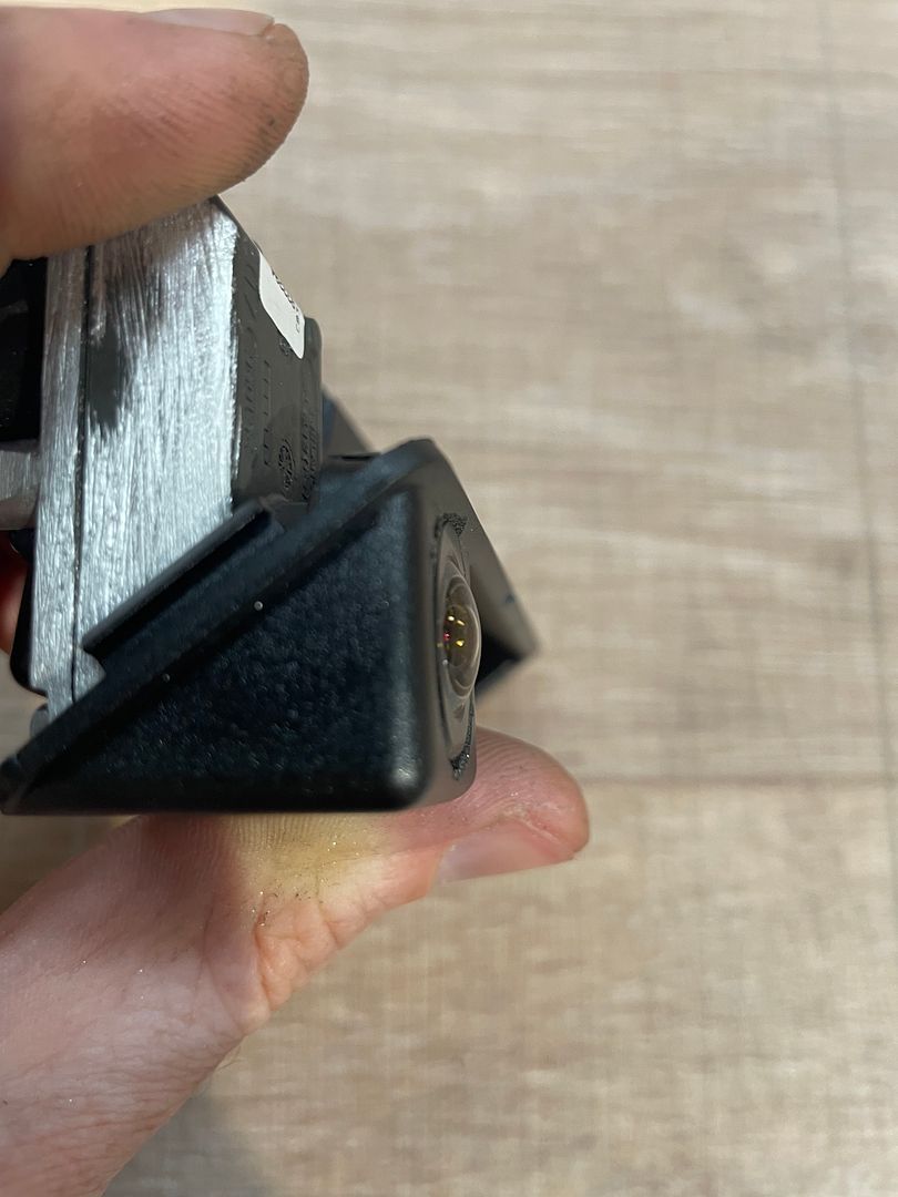
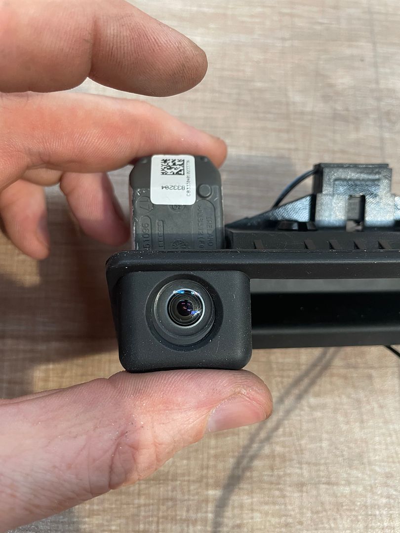
Instead of cutting the handle, I filed down the metal body of the camera to fit the handle. The snug fit also means that the camera is just pushed into place. It is held firmly without any glue or sealant. I have now done ~1500km with the camera fitted (including ~20 Nurburgring laps) and the camera hasn't budged.
This is the handle I purchased from Amazon UK. It looks to be identical to the one Sangria used. If you are looking for a handle, just make sure it has the silicone boot covering the handle.
https://www.amazon.co.uk/gp/product/B07PHWC6DP/ref=ppx_yo_dt_b_search_asin_title?ie=UTF8&psc=1
This is the handle with its camera still fitted and the boot removed:
I dug out the camera from the handle. It came out easily considering it was glued in.
I then split the plastic surround off the F10 camera. I used a knife to cut along the weld line and then a flat head screwdriver to lever the halfs apart.:
I then slowly filed down the body of the camera to make it fit. It took a lot of trial fitting to get it right. The big advantage is that I did not have to cut the handle, weakening it. I did fit away a bit inside the handle, but this was minor. This is how the camera looked when I was finished. I did not go all the way through the housing or seals anywhere so it is still watertight:
This is the small bit of sanding I did to the handle:
And the finished job:
Looks great. If i ever remove my handle i will do this for sure. What did u shave with ?
SaNGRia wroteI used a file. The camera housing is made from aluminium and is very soft. It took me ~30 minutes to do, only because I took my time and did lots of trial fits.Looks great. If i ever remove my handle i will do this for sure. What did u shave with ?
Hi Sangria,
Great your tutorial.
I have an issue with the pdc. I have an E91 LCI 2009 with standard PDC in my car, (only rear) with CiC C1a. Now i changed the PDC for the one I need for the camera, the 9252636. I also ad the PDC_E84.C15 file in the Daten map under E89 and replace the E89SGVT.000 file for the previous one. Now when I try to read or write (SG_lesen or SG_schreiben) to this PDC it says "PDC is not responding or connected". I first wanted to get the PDC working before i install the rest. Is this possible or do I have to connect the TRSVC before I can code the new PDC. What am I doing wrong here? The vendor guaranteed that the PDC module was tested OK. Hope you can give me some leads.
Great your tutorial.
I have an issue with the pdc. I have an E91 LCI 2009 with standard PDC in my car, (only rear) with CiC C1a. Now i changed the PDC for the one I need for the camera, the 9252636. I also ad the PDC_E84.C15 file in the Daten map under E89 and replace the E89SGVT.000 file for the previous one. Now when I try to read or write (SG_lesen or SG_schreiben) to this PDC it says "PDC is not responding or connected". I first wanted to get the PDC working before i install the rest. Is this possible or do I have to connect the TRSVC before I can code the new PDC. What am I doing wrong here? The vendor guaranteed that the PDC module was tested OK. Hope you can give me some leads.
wortel55 wroteIf PDC not responding with OEM plug, something is wrong in the picture. It should work without TRSVC. Try to read on INPA or Tool32.Hi Sangria,
Great your tutorial.
I have an issue with the pdc. I have an E91 LCI 2009 with standard PDC in my car, (only rear) with CiC C1a. Now i changed the PDC for the one I need for the camera, the 9252636. I also ad the PDC_E84.C15 file in the Daten map under E89 and replace the E89SGVT.000 file for the previous one. Now when I try to read or write (SG_lesen or SG_schreiben) to this PDC it says "PDC is not responding or connected". I first wanted to get the PDC working before i install the rest. Is this possible or do I have to connect the TRSVC before I can code the new PDC. What am I doing wrong here? The vendor guaranteed that the PDC module was tested OK. Hope you can give me some leads.
Now i got contact with the PDC. You need to start the car to get the PDC respond. I programed it to default. But now I got a fault in the PDC. It says PDC drop out.When the fault announcement disappears I got the PDC picture in the screen but with no red yellow and green and no beep. When I got the car out of reverse the PDC screen stays on.
Could it be that the pin-out for a E91 is different of that from a E84? I got only 4 wires on the small Black connector. 2 can bus, pos and neg. On the blank connector are 12 wires. 3 each for the 4 sensors. I think that make sense.(only rear PDC so 2 connectors used) But I´m not sure about the black connector.
Does anybody has a Pin-out for the E84 PDC. It would be a great help
Could it be that the pin-out for a E91 is different of that from a E84? I got only 4 wires on the small Black connector. 2 can bus, pos and neg. On the blank connector are 12 wires. 3 each for the 4 sensors. I think that make sense.(only rear PDC so 2 connectors used) But I´m not sure about the black connector.
Does anybody has a Pin-out for the E84 PDC. It would be a great help
wortel55 wroteIf it is only rear , all you need to do is code the PDC default which means keep the .MAN file empty. No need to do rewiring. I have done 3 "only rear" and never had any issue. You do not have to start the car but igntion has to be ON yes.Now i got contact with the PDC. You need to start the car to get the PDC respond. I programed it to default. But now I got a fault in the PDC. It says PDC drop out.When the fault announcement disappears I got the PDC picture in the screen but with no red yellow and green and no beep. When I got the car out of reverse the PDC screen stays on.
Could it be that the pin-out for a E91 is different of that from a E84? I got only 4 wires on the small Black connector. 2 can bus, pos and neg. On the blank connector are 12 wires. 3 each for the 4 sensors. I think that make sense.(only rear PDC so 2 connectors used) But I´m not sure about the black connector.
Does anybody has a Pin-out for the E84 PDC. It would be a great help
Thank you for your help Sangria. I gonna give it a try tomorrow. Will give an update soon.
