1.1KVIEWS
22REPLIES
18APPRECIATES
08-03-2026LAST POST
Hey everyone, I am not sure if I am allowed to do this, but I wanted to share links to our videos here, as some of our more technical videos do not get the love from the algorithm that the more surface-level videos do, and as such, fail to reach most of our audience.

I'll start with our most recent video because former 240 s14's user avatarformer 240 s14 requested more details on our upcoming high-flow oil pump.
11417838311
Bought the oil pump when it was not NLA for like $800 new with a dealer discount.

Sounds like the vanos is using more flow when in the transient states drawing from that oil galley circuit. This makes sense if the DME is requesting min to max then min/max again on both intake and exhaust vanos. This should be confirmed when plotting the pwm signal from the solenoids in those fluttering transient states. Almost sounds like a vanos table tuning issue.

Fact still remains that #1 upper main gets the most wear with two double roller chains pulling nose up. Evidence of this is all the other lower mains getter more wear--especially the lower thrust main. This is exacerbated on #1 upper since it gets compromised supply as you describe. Agreed. Fast revving will have an opposite reaction of the crank wanting to climb up the chain in that area causing crank to have a moment.
Another great test would be looking at s65 engines configured with vanos delete cams setup. Might be a good way to confirm against a control with the stock vanos strategy.
27% more volume, did I hear that right. That mixed with the SRD gears sounds like the way to go versus a dry sump, assuming the pump isn't $10k.

Very excited to learn more about this and appreciate the efforts Chris and Partee are making for our community!

Rubin
RocketyMan wrote
11417838311
Bought the oil pump when it was not NLA for like $800 new with a dealer discount.
Yeah, we all wish they were still that price. Glad you got one before the price hikes! Actually, I was unaware that they were NLA across the board. Last time I looked, they were still available, but were ~$3400. 5150 appears to be the only one with new pumps in stock at $3700.

RocketyMan wrote
Sounds like the vanos is using more flow when in the transient states drawing from that oil galley circuit. This makes sense if the DME is requesting min to max then min/max again on both intake and exhaust vanos. This should be confirmed when plotting the pwm signal from the solenoids in those fluttering transient states. Almost sounds like a vanos table tuning issue.
That is the hypothesis we are currently working with, as stated in the video. We have logged this and have verified that VANOS sweeps, without question, pull oil pressure down. A single VANOS sweep at the end of a dyno run, for example (throttle position from near full advance to near full retard at 8400 RPM), caused the oil pressure to drop from ~75 PSI to 63 PSI for the fraction of a second the VANOS actuator was in motion this was with a daily dry sump oil system- far more oil flow than OEM. We just aren't confident enough yet to treat this hypothesis as a fact, even with the supporting evidence we have so far.
RocketyMan wrote
Fact still remains that #1 upper main gets the most wear with two double roller chains pulling nose up. Evidence of this is all the other lower mains getter more wear--especially the lower thrust main. This is exacerbated on #1 upper since it gets compromised supply as you describe. Agreed. Fast revving will have an opposite reaction of the crank wanting to climb up the chain in that area causing crank to have a moment.
So, without question, the timing chain system does play a role in what's happening here; the catch is that it is symptomatic, not causal.

The thing is that the fact that it is a pair of double roller chains is a very minor issue- everyone points to the S85 as evidence that this is the issue, but the chains are not the only difference, and more so, there is not an inherent difference in chain tension. There is, however, a difference in chain load- you're the first person who has specifically called out the moment created by the transmission of torque through the chain, and that really is the primary force that the crank experiences. That and the complementary moment created by the gear drive for the oil pumps.

(I digressed super hard after this, so I am coming back now in the edit to add: The real difference is NOT the single vs. double roller chain load, it is the fact that the S85 has a separate VANOS pump that does not bleed volume, and therefore, pressure from the main oiling system. All of this is to explain in agonizing detail why the timing chain load is a small potato.)

S65 Valve Timing
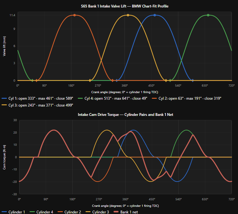
The reason BMW switched to a double-roller system on the S65 is that the valve-actuation forces from the 4 cylinders per cam are more transient. The S65 cam lobes have, at best, a more distinct separation and a complete separation between Cyl 4 VCE and Cyl 2 VOE as a result of its cross-plane crank/90-degree firing order, placing the Cyl 1 combustion event immediately after Cyl 3. Check out this graph- it's easier to see this way. (This is a very generic cam profile for the sake of timing clarity)
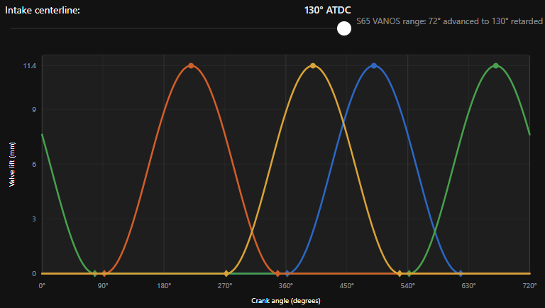
Attached image


S85 Valve Timing
The S85, on the other hand, with 5 cylinders on each bank, with one cylinder (per bank) firing every 144 degrees of crank rotation, has a perfectly even cam event spacing (in terms of degrees of rotation) with significant overlap between cam lobes.
Graph attached below here too)
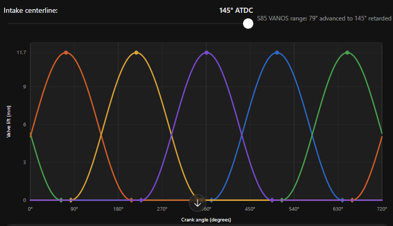
Attached image


How does this matter?
This difference in overlap (per cam, not per cylinder) is why the single-row timing chains were sufficient for the S85, but not for the S65. Attached below is a chart showing intake cam torque load (in brown) and the torque load for each cam lobe pair in Blue, Red, Green, Yellow, and Purple for the S85 at 3000 RPM- most of the miles on these motors will occur in this regime. As such, life expectancies based on cyclic fatigue and frictional wear would likely be calculated here.
(This is an approximation with accurate weights, spring forces, and approximate cam profiles, for the purpose of illustrating the point. This is not an exact model that should be referenced or treated as real-world 1:1 data points.)
S85 Bank 1 Intake Cam Torque Loading Chart
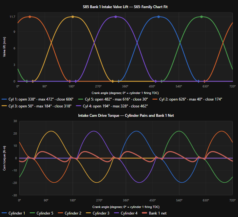
Attached image

Now compare that to the torque load of the S65 intake cam. Notice how there are significant dead zones where no torque is being applied and other areas where torque peaks to the full force of an individual pair of cam lobes- 21.9 newton meters of torque at 3000 RPM. The S65's timing chain must transmit more than 4 times as much torque per cam as the S85's timing chain does at 3000 RPM.
  • Down at 1500 RPM, the S65 cam torque load is up to 23 Nm, and the S85 is down to 2.2 Nm.
  • As RPM increases, the gap does close- at 5,000 RPM, the S65 will see a peak of 23.9 Nm, while the S85 sees a modest 13 NM; the gap has closed to a little under 2x.
  • By 8250 RPM, there is significant parity in peak torque load (S65: 39.3 Nm, S85: 33.8), but a high degree of transience from full load to zero load on the S65 cam, while the S85 has a consistently repetitive load cycle per cylinder.
S65 Bank 1 Intake Cam Torque Loading Chart
Attached image

The reason the relative difference decreases with increased RPM is the result of increasing inertial loads, as the valve velocities and rate of acceleration both increase significantly from 48.93 newtons at 1500 RPM to 1436 newtons at 8250 RPM. As the inertial load becomes the dominant force component the timing chain must overcome, the peaks will start to normalize to each other due to similarities in the valvetrains' mass.

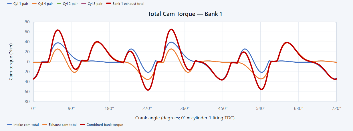
Having said all of that, let's put this into perspective: We can also simulate exhaust cam timing and loads and see that the peak combined cam torque load is 64.3 Nm. The S85 Timing chain is a 06B-1 (simplex) chain- this chain has a maximum working capacity of 1900 N of tensile load. That is a 50% safety margin. Before you consider that the S65 has twice that working load.
Total Cam torque load per bank
Attached image


Total System Torque
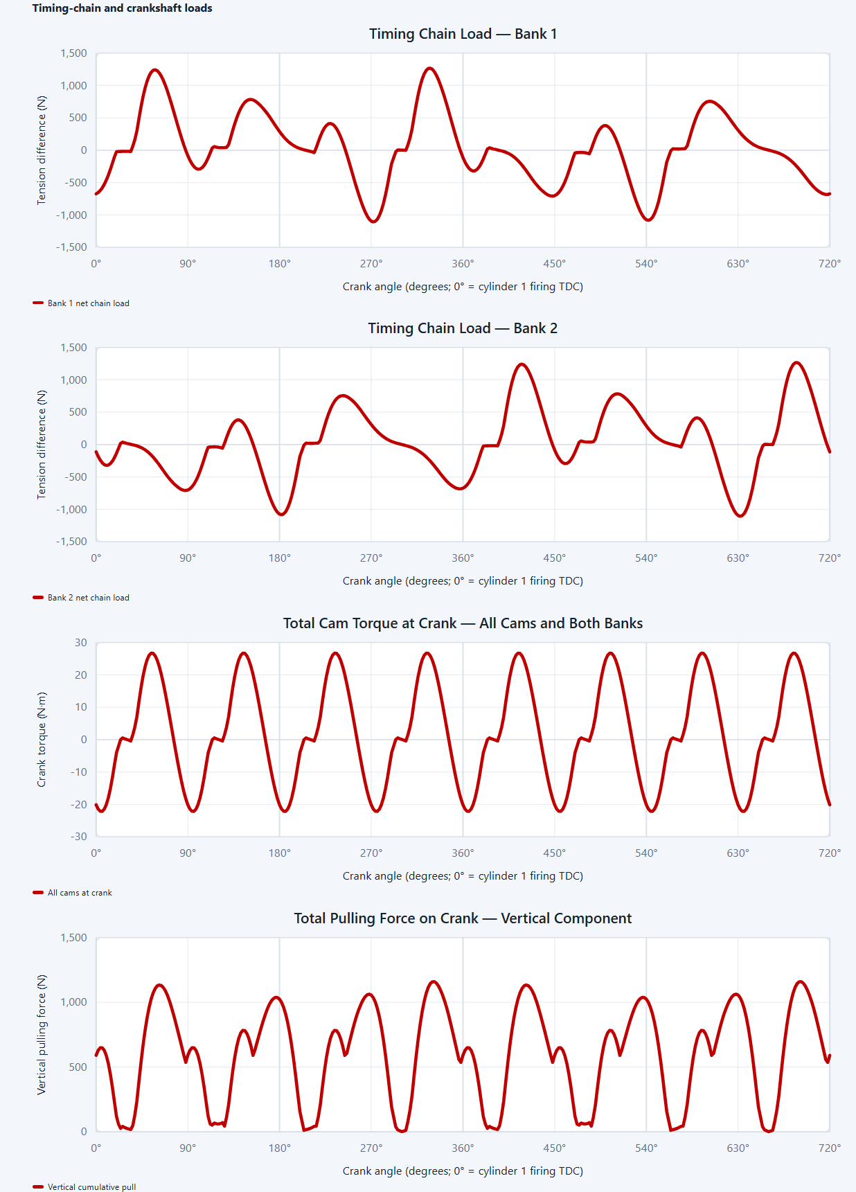
This means there is a peak chain load of 1255 Nm per bank, and I hear you thinking "that means 2500 Nm of total force on the crank!" and It's reasonable to think so, but because the peaks are 90 degrees out of phase, each bank's peak forces are never going to affect the crank at the same time.


S65 Chain loads and Cam Torque at Crankshaft
Attached image

Allow me to explain:
So, what are the actual peak forces the crank will experience, since that is what we are talking about, after all..

Because the crank spins twice for every one cam revolution, and therefore, has a sprocket diameter 1/2 that of the cam sprocket, it takes half the torque to generate the requisite force on the chain. But, as ever, there is more nuance than that, so it is not simply 1/2 the total cam torque. This is because, as I mentioned previously, each bank is 90* out of phase relative to each other. So.... I plotted this out too.

Peak torque at the crank is 27.3 Nm, which, if all of the torque were going straight up (it is not), would result in a maximum pulling force of 1065 newtons... But there is more nuance than that too- simply using peak torque at the crank assumes there is no negative torque being applied to the crank (this happens during valve closing events), and that matters because ANY torque, positive or negative (relative to the crank), requires a tensile load on the chain, which is by definition a pulling force.

Once all of this is considered and factored into the model, it is a (somewhat) accurate representation of the forces the crank will experience during operation, even under the worst-case scenarios.

So, the peak vertical force the crank sprocket will experience (all tensile forces considered) is 1133 Newtons or 254 pounds of force.


Add to that the additional upward force from the oil pump gear 85 N, the pulling forces of the chain tensioners (85N spring preload, plus oil pressure (.55 sq. cm piston, 5.5 Bar oil pressure (high estimate, peak oil pressure), and approximately 1.5 leverage on the tensioning guide. Approximately 180 N of force per bank) multiplied by the leverage of pushing perpendicular to the length of the chain at a low deflection angle, resulting in a chain tension of 347 N. This has to be multiplied by 2x because the chain is a loop, so the real tensile force of each chain is 694 Newtons. A little bit of trigonometry will show that the net vertical force on the crank is approximately 1146 newtons (257lbs.).

To finally mercifully, get to the point:
(All of the following numbers are calculated at 8250 RPM)
Based on all of that, we can reasonably assume that the total upward force on the crank is created by:
  • Peak torque required to drive the cams: 1133 N (Mean torque is 603.7N)
  • The deflection of the geared oil pump drive: 85 N
  • The tension created by the timing chain tensioning loop: 1146 N

Amounts to an estimated total of 2364 Newtons of upward force on the crank. (532 lbf)

As I mentioned in the video, Hydrodynamic lubrication generates OBSCENE force resistance values. A properly formed wedge in 60-weight oil will have a force resistance in excess of 28,000 PSI perpendicular to the direction of the force. The S65 main bearings, top and bottom, both have more than a square inch of surface area (the bottom has FAR more). There is not a chance that the 532 lb. of force on the nose of the crank is sufficient, on its own, to cause the front main bearing to fail. BMW did not switch to a Double roller chain because the forces on the timing chain are so immense; they did it to extend the service life of a part that, if it were to ever wear and fail, would cause catastrophic failure to a point where it is a non-issue.

This upward force is, however, a symptomatic component of the failure mode. The two most important factors for hydrodynamic lubrication performance are the volume of oil flow and the oil temperature at the highest pressure in the wedge.

If flow volume breaks down, the oil temperature in that high-pressure zone goes through the roof, the oil loses its lubricating properties, and metal-to-metal contact occurs.

If you also have 500 lbs pulling up on the nose of the crankshaft while the wedge is barely performing, it only makes sense that you would see severe wear on the top of the front main bearing, especially since the oil pressure falls through the floor at low load/transient throttle, not when the crank is absorbing all 1855 lbf of rod force from BMEP ( that is the mean force throughout the power stroke- peak rod force is well over 8000 lbf that is more than 4000 lbf per main bearing, and a full 8000 lbf through each rod bearing (35,500 Newtons), but we are all concerned about the timing chain tension because its a couple inches in front of the front main.)

I do not believe that oil flow to the front main ever goes to zero (under normal operating conditions); if it did, the front main would seize and spin within a second, and we would not still be talking about this in the big ‘26. What I believe is happening is that oil flow is dropping low enough that (in the front main in particular) the bearing operates on the ragged edge of starving for oil, thus resulting in the front main bearing dying a death of a thousand paper cuts. Each time it happens, the bearing profile gets slightly worse, and performance goes down just a little more, until eventually you destroy your crankshaft and your block, so you have to pay a $5000 core charge in addition to buying a new motor. If you don't decide to scrap the car or toss a junkyard motor into it to do it all over again.

Even worse, when you oversize your rod bearings thinking you're being a safe and responsible owner (just like, quite literally, every single one of our S65 customers), the front main seizes at ~20k miles almost every single time. Hashtag: Tragic.


former 240 s14 wrote
27% more volume, did I hear that right. That mixed with the SRD gears sounds like the way to go versus a dry sump, assuming the pump isn't $10k.

Very excited to learn more about this and appreciate the efforts Chris and Partee are making for our community!

Rubin
27-point-something percent is the joke around here, lol. But yes, that is accurate. Between this and the SRD upgrade, oil flow capacity is increased by 90%. Without meaningfully increasing peak oil pressures beyond 80 PSI or wasting a ton of energy by bypassing excess oil. It simply pumps as much oil as the motor needs at any given volume demand. This might actually pair perfectly with your accusump idea. Although, you will not need it.


We are targeting 2200 or less. Sourcing the internal components is mind-bendingly expensive, but still beats the hell out of new OEM pricing.
Great explanation of the double vs single roller chain necessity. Makes sense that the V10 has much more balanced "pull" on the chain vs the S65.


532 lbs seems like what it would be at a normalized static load @8250 rpms. What about on quick accelerating throttles? I'm not sure how you would go about calculating this force on the chains and then translating it to the crank.
But there would also be a distance that force is applied to on the nose of the crank. Bank 2 being the furthest away from the main #1 upper. And you're right about the trigonometry for SIN(90). This seems rather indicative of nearly all the main bearings I see pulled out of an S65 as the outside edge of the upper main gets the most compromised boundary layer.

I would still challenge the idea that something is going on here as evidence by wear patters of the mains. Again, you see the outside tip of the main #1 upper worn the most while the rear lower thrust bearing is the worst suggesting some sort upward torque around #2 or #3 main acting like a pivot. One would expect only the lower mains to get wear as this would be reactionary just like to the conrods upper bearing on power stroke.

Perhaps you're right that this is just symptomatic. Maybe even as simple as startup-wear for the #1 MB is observed the most when there is no oil pressure until a half second from the engine cranking.


Image hosted on: www.m3post.com

Image hosted on: imagizer.imageshack.com

Image hosted on: www.m3post.com

Image hosted on: farm8.staticflickr.com

These are all borrowed photos from this forum using a quick search.
I think the last photo shows what I'm saying the best. Everyone of these pics you can pretty much guess which one #1 upper MB is based upon the wear pattern.
Chris and I went through his analysis in fascinating detail yesterday. I'll let him respond to the notion that he only calculated "static" load on the crank.

I think the most helpful point Chris makes is that wear on the bearings doesn't indicate a cause, but rather a symptom, or a consequence, of the cause. The cause is the breakdown of the hydrodynamic wedge and the massive resistive force it generates. The force exerted on the crank takes out the No. 1 main bearing only when the hydrodynamic wedge breaks down. Under normal operating circumstances, there is no way that force even makes a dent in the resistive force generated by the hydrodynamic wedge.

So then the question is why the wedge breaks down. As we note in our lengthy recipe video, the proximate cause is the lack of sufficient oil flow, which is in turn caused insufficient "headroom" in flow from the oil pump. The witness marks in S65 oil pump after S65 oil pump show the same thing: the "variable flow" pump is almost always maxed out, so it lacks the additional flow necessary to handle vanos sweeps at critical moments, such as the one Chris identifies above.

But why is this phenomenon so concentrated on the No. 1 main bearing? The No. 1 main bearing is the only main bore that lacks its own oil galley. The No. 1 main bore shares its oil galley with the chain guides. No other main bore does. And, as noted above, the upward tension on the crank causes the lack of sufficient oil flow and the resulting wear and ultimately metal-to-metal contact, to manifest itself first on the No. 1 main bearing, meaning that is the bearing and bore that suffers from low oil flow for the longest period of time.

A couple of corollaries to draw from all of this. First, there's nothing inherently wrong or defective with the S65 timing chain. It's fine so long as the main bearings see sufficient oil flow in all circumstances, including vanos sweeps. Second and similarly, there is nothing wrong with additional clearance for the S65 rod bearings. So long as the S65 oil pump provides the additional flow required to maintain the hydrodynamic wedge in those larger rod bearing clearances AND in the main bearing clearances even when vanos is sucking off oil like crazy, all is well.

Finally, I know this sounds like an advertisement for our oil pump. I assure you that is merely a nice, but completely incidental consequence of Chris's analysis. We all dove into this (and Chris became obsessed to an economically obscene point!) because we wanted to find a scientifically supportable hypothesis for No. 1 main bearing failures in the S65. We believe we have done that and more. Now to test our pump and turn it into experientially corroborated theory.

As is appropriate, Chris's own car (and his brother's) will serve as the test subjects. We are confident the pump design will cure the issue, especially when combined with the SRD gearset. Race cars will continue to benefit, of course, from a Dailey Engineering dry sump to ensure continuous oil pickup in the highest g cornering, but not because of the flow or pressure generated by a Dailey. For that we believe our pump does the trick.

Be well, and go fast.

--Peter
RocketyMan wrote
Another great test would be looking at s65 engines configured with vanos delete cams setup. Might be a good way to confirm against a control with the stock vanos strategy.
That test subject is currently under construction for a client whose vanos delete S65 blew up after a single track session for reasons unrelated to oil flow (detonation took out the top ringland of a couple of pistons).

--Peter
Thanks, Peter, for your responses. Interested to learn more about the VANOS delete and oil pressure throughout the RPM band vs the control--using the stock VANOS setup. Perhaps a VANOS delete would in fact cause the oil pump to not be at the max pressure span the entire time and allow some headroom.

Another caveat that I don't think was mentioned about MB #1 is that this journal only supplies one conrod journal vs the other MB supply two conrod journals--barring the rear MB journal also supplies only one conrod journal. But if we're going with this hypothesis, the conrods leakdown rate probably isn't as great as the chainguides and VANOS.

Also, somewhere around MB #3 has two lines going up to the heads for all the cams and "lifters" for both banks. It sure would be nice to know emperically which component takes the most flow and pressure--sneaky suspicion being the VANOS.
RocketyMan wrote
Another caveat that I don't think was mentioned about MB #1 is that this journal only supplies one conrod journal vs the other MB supply two conrod journals--barring the rear MB journal also supplies only one conrod journal. But if we're going with this hypothesis, the conrods leakdown rate probably isn't as great as the chainguides and VANOS.

Also, somewhere around MB #3 has two lines going up to the heads for all the cams and "lifters" for both banks. It sure would be nice to know emperically which component takes the most flow and pressure--sneaky suspicion being the VANOS.
Excellent points! Love the group think.

--Peter
I just want a Dailey dry sump for oil consistencies.
Can you please upload a video that goes over, in detail, the build process and differences between your S65 packages? Would be a great watch. Gracias!
THEROK wrote
Can you please upload a video that goes over, in detail, the build process and differences between your S65 packages? Would be a great watch. Gracias!
Sure. The upshot is that the Better than Stock Budget vs. High End difference is solely in the pistons: the budget version uses Mahle off the shelf 92.5mm pistons and rings, whereas the high end goes to 94mm and uses our custom piston and BMW S62 rings, just as our stroker does. The stroker simply adds the Arrow billet crank with an 82.7mm stroke.

Each build comes with metal bolt on vanos covers, aluminum spark plug tubes, etc. We don't automatically include aluminum valve covers, but can do so for the retail cost of the covers.

I agree that a video about all of this would be great. Appreciate the feedback.

--Peter
omgzirra_exe wrote
I just want a Dailey dry sump for oil consistencies.
We’ve installed them on customer cars. For dedicated track only cars, they make sense. Until now a true dry sump solution was the only viable option protect your motor in my opinion, but there are necessary compromises to make them work: AC delete, obviously, and then routing of the lines is a GIANT PITA, plus the breather from the oil tank puts out a ton of stink, if not routed out of the car and into a place that carries the smell away from the cabin. That’s to say nothing of the price point of the kit, and even more the cost of installation in either money or time. Last one we did took more than a week of the shop’s full attention.

The next biggest pain point of a Dailey dry sump is the fact that you need to idle your car at 1000 RPM at minimum. Due to the shape of the bottom of the S65, you need to run a relatively long drive belt. This is problematic because it shakes around like crazy during operation if you drive it too fast. I personally spoke with Bill on the phone about this issue because our last client wanted to keep his ~600 RPM idle. My plan was to change the cogs that came with the kit to overdrive the pump a little and his response to my suggestion was, and I quote, “tell your client that it’s a race car and race cars idle at 1000 RPM. We spent a lot of time developing this kit, and if you spin that belt any faster, you risk throwing a belt. I’m not going to tell you what to do with your setup, you bought it, but I do not recommend changing it.”

At ~600 RPM, hot oil pressures were as low as 10 PSI.


Our pump, on the other hand will supply Higher oil pressures, at idle, than the OEM pump and similar peak oil pressures thanks to the fact that it operates on the same principle as the OEM variable displacement system.

Additionally, on the track, seeing high lateral G forces, the pump should not have any pickup issues whatsoever. I foresee no need for baffles or accusump solutions whatsoever. The OEM oil pan is a spectacular piece of kit- it was BMW’s first attempt at a sort of quasi dry sump system- when the oil pan is installed on the engine, it seals the entire oil reservoir from the windage tray, minus the small drain window in the center of the reservoir. I filled the oil pan with 7 quarts (remember it takes 9.5 to fill the motor) of water to simulate how much Gforce is tolerable before the oil level comes within 2 inches of the oil pickup. IIRC, it was 66*. Let’s say it was just 60*, though- that’s still 2G to get the oil level within 2” of the oil pickup opening.

As long as the pump is capable of flowing enough oil, which ours will be, starvation issues will be a thing of the past.
RocketyMan wrote
Great explanation of the double vs single roller chain necessity. Makes sense that the V10 has much more balanced "pull" on the chain vs the S65.


532 lbs seems like what it would be at a normalized static load @8250 rpms. What about on quick accelerating throttles? I'm not sure how you would go about calculating this force on the chains and then translating it to the crank.
But there would also be a distance that force is applied to on the nose of the crank. Bank 2 being the furthest away from the main #1 upper. And you're right about the trigonometry for SIN(90). This seems rather indicative of nearly all the main bearings I see pulled out of an S65 as the outside edge of the upper main gets the most compromised boundary layer.

I would still challenge the idea that something is going on here as evidence by wear patters of the mains. Again, you see the outside tip of the main #1 upper worn the most while the rear lower thrust bearing is the worst suggesting some sort upward torque around #2 or #3 main acting like a pivot. One would expect only the lower mains to get wear as this would be reactionary just like to the conrods upper bearing on power stroke.

Perhaps you're right that this is just symptomatic. Maybe even as simple as startup-wear for the #1 MB is observed the most when there is no oil pressure until a half second from the engine cranking.


Image hosted on: www.m3post.com

Image hosted on: imagizer.imageshack.com

Image hosted on: www.m3post.com

Image hosted on: farm8.staticflickr.com

These are all borrowed photos from this forum using a quick search.
I think the last photo shows what I'm saying the best. Everyone of these pics you can pretty much guess which one #1 upper MB is based upon the wear pattern.
To your first question, my calculation did not only consider static loading as, where reciprocating ICEs are concerned, there is almost no such thing as a static scenario. The closest to a static environment that exists (on an exceedingly short timescale), in my opinion, is the intake track upstream from the plenum. Even then, though, pulse wave dynamics matter to a small degree. Internally, you could consider the coolant loop a static scenario, and maybe (in any other engine) the lubrication system.

I digress.

Back to the original point- no, I was not only considering a static load. The thing is that out of the sum of all forces acting on the crankshaft snout- the inertial load of the acceleration of the camshaft, the acceleration of the cam gears, and the acceleration of the chains are minuscule. Like, in the tenths of a horsepower range. As far as the acceleration forces of the valves, springs, lifters, retainers, etc. are concerned, these add up to be quite significant, which is why I called them out specifically.

The catch, however, is that those forces are entirely independent of the crank’s rotational acceleration. Each load cycle of each cylinder’s valves is independent of every other load cycle preceding or subsequent cycle, except where they overlap with other valve open events. The effect of the acceleration of the camshaft (tied to the rising RPM of the crankshaft) is multiple orders of magnitude lower than the acceleration forces imparted upon the valves (and related components) by the profile of the cam lobe; furthermore these forces are constructive, but not multiplicative, therefore the rate change of the cam over the minuscule reactive force acceleration of the valve system is simply added to it.

Having said all of that- these things were considered in my model. When you break the components of the system out individually, study all of the dynamic loads they experience on an individual basis, and then put them all together one by one, it becomes fairly straightforward. The hard part is simply identifying every force generated by the deceptively complex system. To figure out the load generated by accelerating the chain? You simply need to identify the mass of the chain, identify the rate change of the chain at peak engine acceleration based on the radial distance of the center of the chain on the crank’s sprocket, and do some basic math. Not quite 100% of the chain’s acceleration force will be reacted by the crank, but most of it will, so I assumed 100% would be.
The cams and sprockets are a bit more tricky. I had to model these in CAD to identify their radial center of mass in order to identify their inertial load, but once this was done, it was extremely simple to figure out their actual inertial load.

Upshot of all of that is as I said, the loads mentioned above are the peak loads. In any 720* cycle at 8250 RPM, the crankshaft loads will vary anywhere from the peak mentioned above to approximately 40% less pulling force on the crankshaft.

Regarding the pictures you provided-
Like Peter said, we are not arguing that this isn’t the failure mode that is taking out most engines now. That’s why I did this research and subsequently designed our oil pump. We tear apart a LOT of these motors and we see this exact wear pattern 100% of the time.

But we are still absolutely confident that this issue is entirely symptomatic.
Lots of people have mentioned the distance from the front main bearing to the timing chains as the cause of this problem- that was largely why I did the research above. But the moment applied to the crank about, while significant, is still insufficient to cause this wear on it’s own. The lever, if you imagine the length of the crankshaft to be one, is not going to multiply the pulling force of the crankshaft by even 2x (the actual lever created probably has a sub 1.0 factor, but in all honesty, there are entirely too many dynamic factors at play here to know for sure, so 2k is the extreme worst case I am operating with). Realistically, in the worst case scenario I can imagine being possible, the fulcrum about which the crank will be rotated would be the #1 main bearing with #s 2,3,4,and 5 each applying a reactionary force against the timing system’s pulling force. The amount of deflection on the snout at this level of load is less than 0.0002” at the furthest point of the timing gear from the #1 main (assuming 100% of the load were applied to this same point- worst case (and impossible) scenario), and an angular deflection of .001 degree, again, at the furthest point of the timing gear. Inside the main bearing, the deflection is effectively zero.

Now, across the crankshaft, while the crank itself will have virtually zero bend, based on the evidence from the bearings, the entire thing appears to be deflecting around the front main under the low oil flow conditions mentioned previously.

As mentioned previously though, none of the forces imparted on the crankshaft are sufficient to overcome the pressure resisting properties of hydrodynamic lubrication. This is just an objective fact. It appears, based on all of our research, all of these issues are largely driven by insufficient oil flow under specific conditions. That is what our oil pump solves.
Very interesting information here. It reminds me of the increased oil flow discussions surrounding the BE bearings from a while back.

Would any increased oil flow due to higher clearance RBs have an affect on maintaining the wedge of the mains? Obviously not to the extent of the pump / gear solution but I would want to believe it would have a more consistent flow/wedge than with stock clearanced RBs?
PapaMurph wrote
Very interesting information here. It reminds me of the increased oil flow discussions surrounding the BE bearings from a while back.

Would any increased oil flow due to higher clearance RBs have an affect on maintaining the wedge of the mains? Obviously not to the extent of the pump / gear solution but I would want to believe it would have a more consistent flow/wedge than with stock clearanced RBs?
I know the exact thread you're referring to. In another thread where a user asked a question about the RE overdrive kit, that thread was brought up, which prompted me to take a closer look at their data. Under closer scrutiny, that whole write-up reads more like elaborate marketing fluff than the analysis they wanted it to seem.

My analysis of that thread can be found here:
https://www.m3post.com/forums/showpost.php?p=32666957&postcount=33

The original thread was extremely wordy and made some absurd assumptions that confirmed an obvious bias. They claim they only saw a 3 PSI oil pressure drop and declared that negligible. That claim in and of itself is absurd in my opinion.
They changed ONE single variable in a system that has:
  • 5 Main Bearings
  • 8 Rod Bearings
  • 8 oil squirters
  • 2 timing chain lubrication feeds
  • 20 cam bearings
  • 32 lifters
  • 4 VANOS actuators

If one single variable changed the pressure of the entire system by 3 PSI, the change in that one sub-system (main bearings and rod bearings due to the feed path being through the crank), then it must be some multiple of that.

The oversized bearings absolutely increase the flow in the Rod bearings, but not the Main bearings.

The rod bearings are, sort of, the cap for the main bearing system. If you have extremely tight clearances in the mains, and loose clearances in the rods (or vice versa), you have an imbalanced system that will eventually fail due to the flow imbalance. Unless you have enough flow that appropriate pressures are maintained across the board.

In short, the higher clearance rod bearings, in this case and according to the evidence we have seen, contribute to the breakdown of the wedge in the mains and drastically improve bearing performance in the rod bearings.

It is our opinion that the new gold standard for reliability will be increased rod AND main bearing clearances paired with the SRD overdrive kit and our oil pump.

The next best option would be new bearings across the board with stock clearances and the SRD pump- you can get away with the SRD gears and oversized clearances; we have built engines like this, but we took the time to develop this pump for a reason. We want to see better oil pressures still.
Chris, I read the entire thread, and pardon me if I missed it (it could be staring me straight in the face) but was the tendency of a timing chain (or any flexible loop of mass) to want to follow a circular path the more it spins taken into account as far as uplift on the crank snout? I would imagine all else being equal, just having double the timing chains for S65 versus S85 would put twice that upward force on the crank at any given RPM. I mean regardless of chain tension or chain tensioners. Am I making sense? Was this already included in the 532 lbf number communicated earlier?
Hoping when Chris wakes up and peels his face off of the keyboard he will continue/edit his reply. :bellyroll
BenFenner wrote
Hoping when Chris wakes up and peels his face off of the keyboard he will continue/edit his reply. :bellyroll
Hahahaha thanks for understanding me so well !

To finish what I was saying earlier-
Great question!

Before I get too deep into it, let's do a TL;DR- Chains are surprisingly unintuitive lol.

So, to properly answer your question- no, you did not miss it anywhere; I did choose to omit this detail for two reasons:
One, the post was already incredibly wordy, so I did not want to add any unnecessary detail.
Two, it was an unnecessary detail because the net force of the chain on the crankshaft is zero.

As I said, surprisingly unintuitive. The thing is that 100% of the tension in the chain as a function of reactive centrifugal force is contained within the chain itself. For every newton of force it requires to turn the chain around sprocket A, there is an equal and opposite force happening at the opposing side of sprocket B.

The way that made it click for me was visualizing a single link of the chain as a spacecraft and thinking about orbital mechanics rather than a chain.

Where the chain uses internal tension to "orbit" between two sprockets, a spacecraft uses gravity to maintain its "loop" about two bodies. A chain with two sprockets can be imagined as a two-dimensional version of an orbit- the smaller sprocket being the periapsis and the larger sprocket being the apoapsis

A spacecraft needs no outside force (beyond gravity, obviously) to orbit- even in a HIGHLY elliptical orbit. So too with a chain; even though its path may be far from its natural circle, its own internal tension maintains an inherent balance, except instead of gravity, it is its own internal tension resisting the outward acceleration.

But the question remains- does it not require some amount of force to distort the chain around the sprockets instead of allowing it to follow its natural circle?
Yes- tension. It is necessary for there to be a static tension element in order for the chain to maintain its distorted path. You can accomplish this one of two ways: you can either set the chain length to an optimal length for the distance between it's sprockets (as you would see on a fixed gear bicycle), or you need some sort of tensioner guide (as is seen in almost all timing chain systems), or a tensioning sprocket (as is typically seen on a mountainbike's rear derailer- this is especially necessary due to the wide range of sprocket diameters in that system). In some cases, tensioners are eschewed where they would otherwise be beneficial, such as a dirtbike's final drive chain, due to the immense forces the chain must transmit being far more (particularly in terms of shock loads from situations such as wheel hop) than any lightweight tensioning system could tolerate, making it unfeasible; resulting in much much shorter replacement intervals due to a necessity for a looser fitting chain causing significantly more wear on the chain itself and the sprockets.

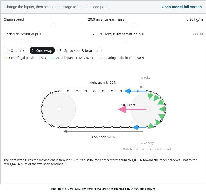
Back to the point- the preloaded tension on the timing chain is the only outside force the chain inherently applies to the crank. All of the inertial forces are self-contained- there are extremely high accelerative forces while the chain is changing direction around the sprocket. Still, the centripetal force is entirely generated as a reaction force to the chain's tension (which increases drastically as velocity increases). The linear tension within the chain is generated entirely (except for the pretension from the tensioning guide) by reactive centrifugal force. All of these forces are generated, as mentioned above, by the chain's velocity, which is driven by the engine's RPM, creating a peak velocity of just over 22.5 meters/second at 8400 RPM. The upshot of all of that is that if it were not for the tension in the chain, the chain links would simply fly right past the sprocket rather than curve around it. They are imparting no inward pulling force to the sprocket as they go around it.

If you're having a hard time visualizing this, reasonably so- I do too. Even though I understand the theory, it is counterintuitive and complex enough that I had a hard time seeing it in my mind- I had one of my AI agents build this interactive model, build a web page to host it, and told it to cite its sources on the web page. I never let AI guide my decisions, but it is SPECTACULAR for things like building this visualization model and finding relevant research publications.

Check it out:

If you want to set up the exact scenario described in my first response, the slack side residual pulling force is just under 350 N, the torque-transmitting pull is just under 1150 N (per bank), the closest standard-size chain I could find is a BSRC size 06B duplex which has a mass of 0.8kg/meter, and the peak chain velocity is just over 22.5 meters per second. The accelerative force of the chain is included in the 1150 N pulling force.


Image hosted on: chain-drive-force-transfer.chris484270.chatgpt.site


Click the diagram to open the interactive chain-force model and full technical explanation.


RocketyMan's user avatarRocketyMan I went back through my notes and found the exact numbers: the reaction force of accelerating the chain from 0 RPM to 8400 RPM in 1 second (which is an unrealistic worst-case scenario, and represents a higher rate of acceleration than will ever be experienced by the motor in the real world) is 5.72 newtons (1.28 pounds force) per bank. 0.148 Nm of torque ( 0.1 Ft Lbs), and a peak of 0.168 horsepower. It is relevant and was included, but as I said above, to Ben, that post was already LOONG. I was trimming fat wherever I could.

Back to the original point, Ben, when you have the model set up correctly, you will see that the total pulling force on both of the sprockets is approximately (because we are using rounded numbers in the model) the total pulling force that each bank applies to the crank toward that bank's intake cam.

I hope this helps make sense of what I am saying here.

I know that the most widely believed and accepted explanation for front main bearing failure is the extra weight of the duplex chains and/or the added distance from the front main bearing due to the additional chain thickness; I believe this is because it makes intuitive sense to most people. I know that the position we are taking on this is in almost direct opposition to the consensus of the community at large.

That is why I am willing to take the time to show our work, show that we have done the research, and explain the conclusions we have drawn.

The vast majority of vendors in the aftermarket operate on experience-based assumptions, best practices, and doing what is known to work.

That is not necessarily a bad thing- we rely on those things too. Our near century's worth of cumulative experience in building engines, manufacturing products, research and engineering, and building fast, reliable cars is one of our most valuable assets.


The issue comes when you let experience, known processes, and best practices dictate (rather than guide) engineering and design decisions. When you do that, you remove any opportunities to look at a problem from a different perspective. When I first pitched my theory to Ray, our engine builder with 40 years of experience building extreme high-end racing engines and vintage Ferrari engines, he quite literally laughed at me. He said that there was zero chance whatsoever that any OEM would ever build a motor on such a knife-edge of oil flow for any reason. I asked him to look at the evidence we were seeing- the highly unusual wear on the top side of the main bearings, the fact that it is ALWAYS #1, the fact that the witness marks in the oil pump show that the oil pump spends 95% of its time operating at full flow rather than partial flow as it is designed to do. The fact that the oil pan is designed so well that it prevents oil pickup issues except in the most catastrophic situations was all irrefutable. So then, all those months ago, I started working through the forces and loads the front main experiences- the things that I am showing to you all now- and then getting the whole braintrust together and asking them to pick my claims apart. If at any point I was asked a question I did not immediately have an answer for, that was a Red flag- I did not yet have a complete understanding of the entire system, and therefore had more research to do.

Now we are here. The part is designed, and the latest prototype is sitting on my desk. The next step is to finish machine the 3D-printed aluminum body, drop my oil pan, and go testing.
Chrisyphus wrote
the net force of the chain [with respect to inertial self-shaping] on the crankshaft is zero.
Got it.

To see if I understand the gist of this correctly, you're telling me that in the fixed-gear bicycle example (two sprockets, one chain, no tensioners) the sprocket shafts would each experience an inward force that would grow with RPM since the chain would want to tend toward a circular shape.

But all of that force is transferred to any chain tensioner in the system (either jockey wheel/derailleur or frictional chain guide) if one exists?

That's how I'm reading your post right now. Do I have it?


Or is this self-shaping force not a real thing and I just made it up?
Or maybe the angle with which the chain leaves the sprocket has something to do with this and perfectly 180-degree turns of a chain don't impart any self-shaping force but all other angles do?
BenFenner wrote
Got it.

To see if I understand the gist of this correctly, you're telling me that in the fixed-gear bicycle example (two sprockets, one chain, no tensioners) the sprocket shafts would each experience an inward force that would grow with RPM since the chain would want to tend toward a circular shape.

But all of that force is transferred to any chain tensioner in the system (either jockey wheel/derailleur or frictional chain guide) if one exists?

That's how I'm reading your post right now. Do I have it?


Or is this self-shaping force not a real thing and I just made it up?
Or maybe the angle with which the chain leaves the sprocket has something to do with this and perfectly 180-degree turns of a chain don't impart any self-shaping force but all other angles do?
Close but not quite.

TL;DR: Chains, if entirely isolated from outside influence and friction, will follow the path they were pulled in. The math says that if you could pull a chain through the air and write your signature, all but the last few links would perfectly follow the path of the first link. Internal tension creates a rigid looking structure.

The only net forces the chain itself can impart on the sprockets that result in them being pulled toward each other are static tension and chain whip.

In a fixed gear bicycle, if set up right (with a small amount of slack), the static tension would be near zero outside of the force of gravity pulling the chain spans toward the earth, which is a very near-zero value on a bicycle chain.

The chain's tendency to follow a circular path is almost entirely the result of friction and drag. A circle will naturally form over time (if momentum is infinite) in an unsupported (as in floating in 0g) chain because, with no outside intervention and given enough time, all of the forces in the chain will work to balance themselves.

In all chains, while spinning, the chain is inherently balanced except for drag. The acceleration (as a result of reactive centrifugal force) of any given point in the chain is balanced and reduced to zero within the chain itself through the chain's internal tension, but frictional losses are focused at the tight turns around the sprockets. Remove them and give enough time, and the chain would eventually form a loop.

I just now noticed your grey blurb at the end of the quoted post lol.

It is not made up, as mentioned above, but it is widely misunderstood. If you know Steve Mould on YouTube, the man 10Xd the size of his audience by explaining the unintuitive behaviors of chains lol. His first couple of videos are partially responsible for my inordinate level of chain dynamic education- I found one of them while in a bit of a rabbit hole years ago and thought "nah, that can't be right" and started reading about what is now known as the Mould Effect. The fact that the phenomenon demonstrated in his video is named after him should be a solid hint that the sum of my casual research at the time amounted to me learning how little I knew about the topic lol. IIRC, his key contribution to the topic was his intuition that friction was the force that caused the chain to seemingly levitate on its own (I could be wrong about that; it's been years now).

Check out this video:
It was the first one of his that popped up when I googled his name. It has a perfect explanation for what I have been trying to say starting at about 5:55 in the video (but I recommend watching the whole video; it's great). Steve even shows a simulation of a chain where it behaves exactly as the chain in the ISS does in real life when friction is turned on and exactly as the math says it would without friction. The fact that removing friction gets the simulated chain to behave as the math says it would when the same physics engine produces a behavior nearly identical to what is observed in the real world definitely supports the theory that it is ONLY friction that drives a chain into a circle.


Regarding the forces absorbed by the tensioners and guides: As I have established in the paragraphs above, no centrifugal forces are escaping the chain that are from the chain itself- the tensioners and guides do what their names say and nothing more.

The tensioner guarantees there is no slack in the chain whatsoever, and both guides do exactly that- they guide the chain along a path to ensure it does not have the opportunity to whip under shock loading.


Thanks for another opportunity to get into the weeds, Ben!